Image forming apparatus using an asymmetric wave pattern of developing bias voltage

a technology of developing bias and forming apparatus, which is applied in the direction of electrographic process apparatus, instruments, optics, etc., can solve the problems of easy affecting of small particle size toner, and achieve the effect of preventing absorption and white loss, and preventing the development of adhesiveness of toner from lowering

Inactive Publication Date: 2001-09-04
KONICA CORP
View PDF25 Cites 25 Cited by
  • Summary
  • Abstract
  • Description
  • Claims
  • Application Information

AI Technical Summary

Benefits of technology

An object of the present invention is to prevent the absorption and white loss, and to provide an image forming apparatus to prevent the developability (toner adhesiveness) from lowering.

Problems solved by technology

However, the small particle size toner is easily affected by the electric line of force.

Method used


Image

  • Image forming apparatus using an asymmetric wave pattern of developing bias voltage
  • Image forming apparatus using an asymmetric wave pattern of developing bias voltage
  • Image forming apparatus using an asymmetric wave pattern of developing bias voltage

Examples


example 2

Next, the present invention will be explained about the second example.

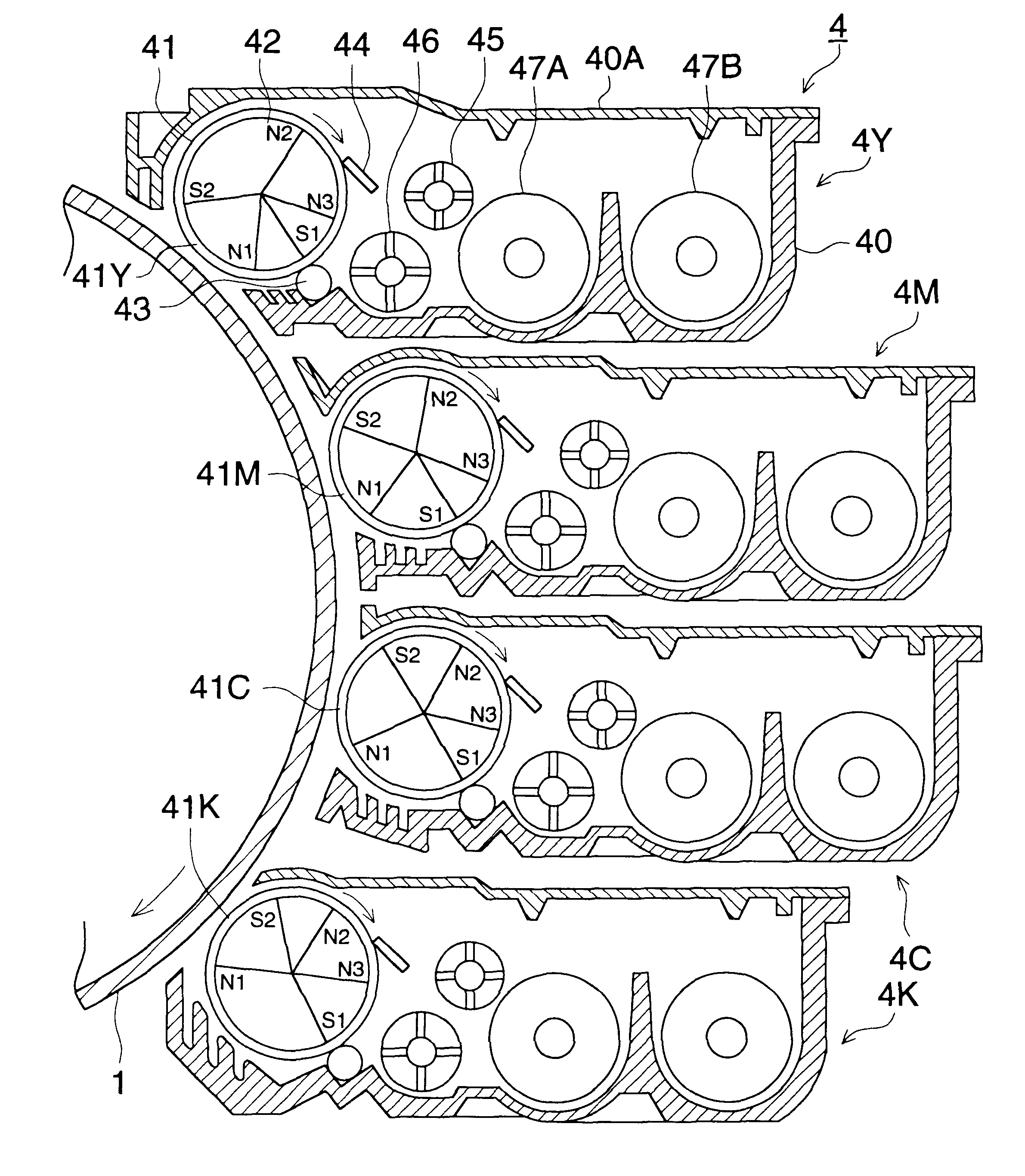
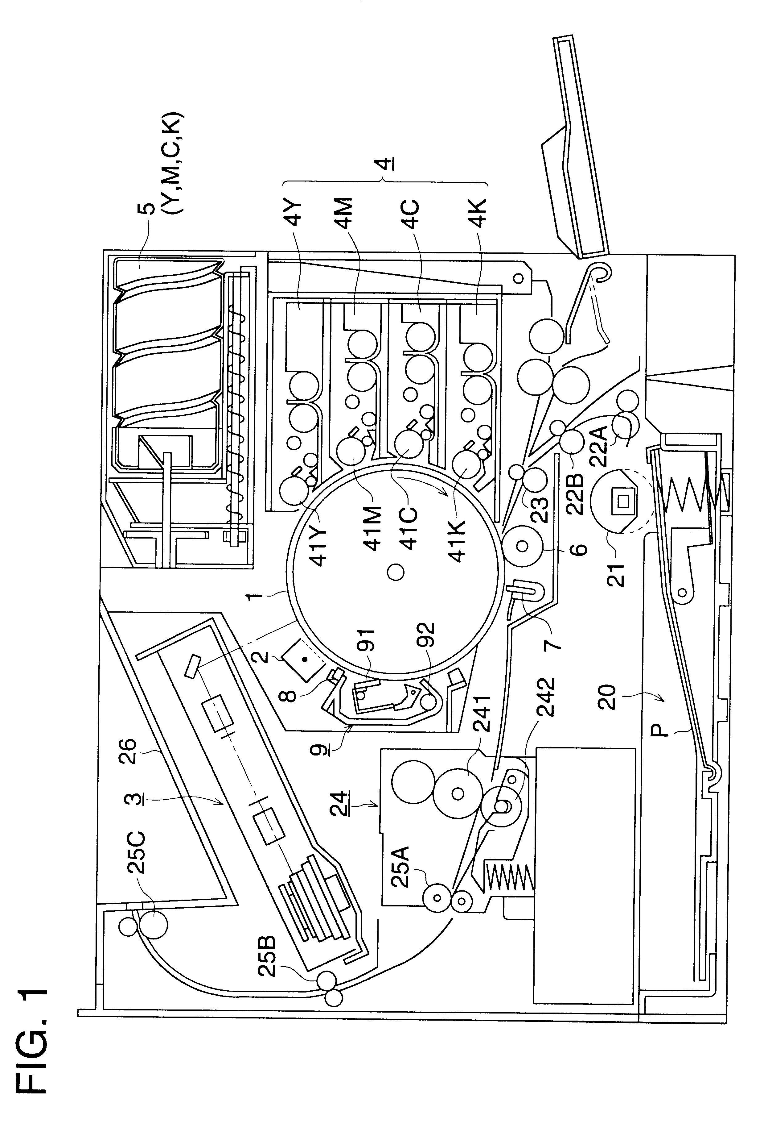
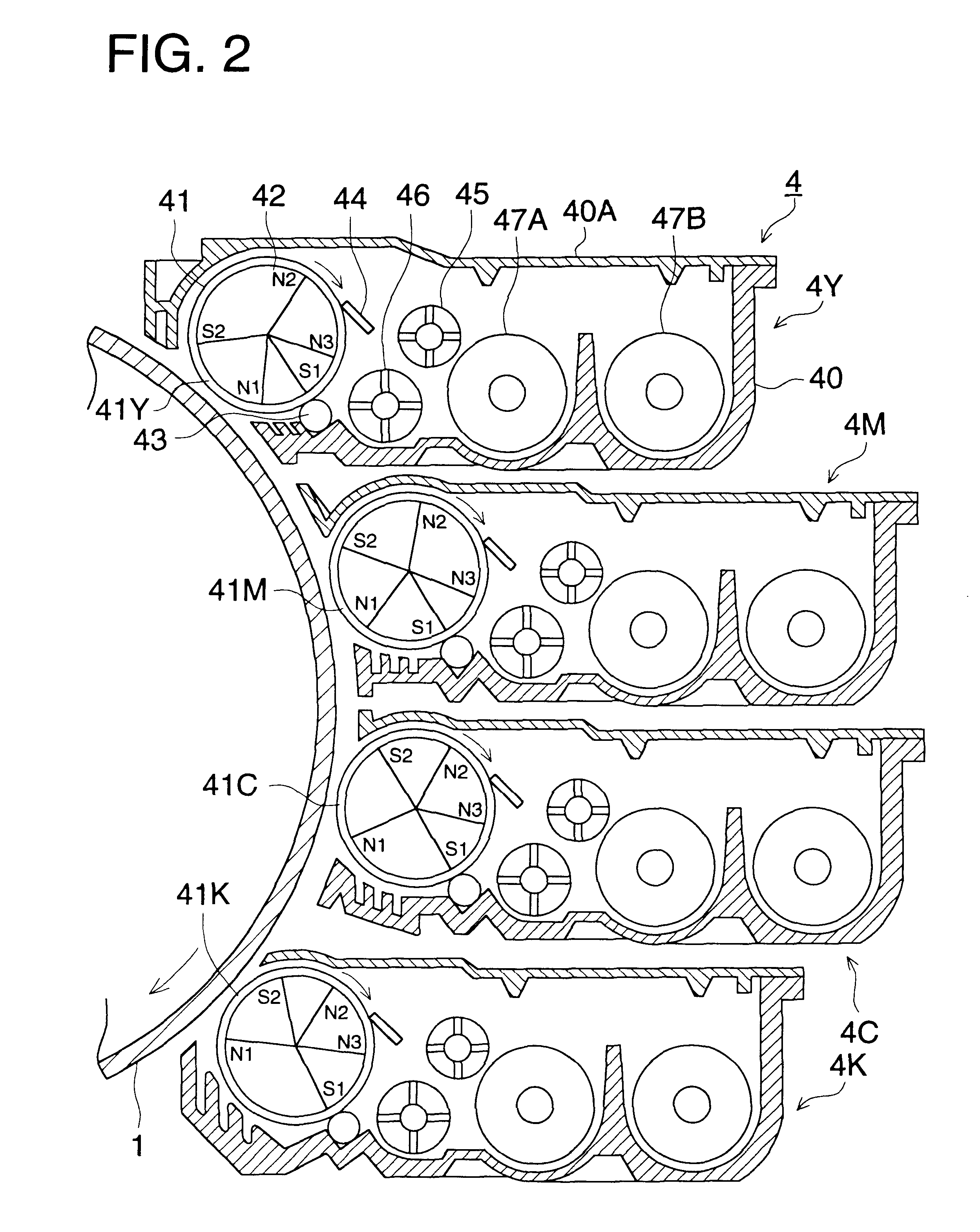
The experiment is carried out as follows. Development is carried out under the following developing conditions and image formation is carried out. The image forming apparatus shown in FIG. 1 is used for the image formation, and the developing apparatus shown in FIGS. 2 and 3 is used for development. The following conditions are set, the toner conveyance supply amount is made variable, development is carried out by the above-described operations, and images are evaluated.

Incidentally, as the image forming apparatus according to the present example, Konica KL-2010 color printer (made by Konica (Co.)) modified machine, shown in FIG. 1, is used, and the outer diameter of the developing sleeve 41 is .phi.18 mm, and the outer diameter of the photoreceptor drum 1 is .phi.100 mm.

Setting conditions of the development processing are as follows.

The closest proximity distance d between the

photoreceptor 1 and the developing s...

example 3

The present invention will be explained about the third example.

Development is carried out under the following developing conditions and image formation is carried out. The image forming apparatus shown in FIG. 1 is used for the image formation, and the developing apparatus shown in FIGS. 2 and 3 is used for development. The following conditions are set, the development method is respectively set to the inter-polar development and top-polar development, development is carried out by the above-described operations, and images are compared and evaluated.

Incidentally, as the image forming apparatus according to the present example, Konica KL-2010 color printer (made by Konica (Co.)) modified machine, shown in FIG. 1, is used, the outer diameter of the developing sleeve 41 is .phi.18 mm, and the outer diameter of the photoreceptor 1 is .phi.100 mm.

Setting conditions of the development processing are as follows.

The closest proximity distance d between the

photoreceptor 1 and the developin...


PUM


Abstract

An image forming apparatus, including: a charger, arranged around an image carrier, for charging a surface of the image carrier; an exposure device, arranged around the image carrier, for exposing the surface of the image carrier, after it is charged by the charger, and for forming an electrostatic latent image on the surface of the image carrier; a developer device, having a developer carrier and arranged around the image carrier, for carrying developer with which the electrostatic latent image is developed so as to obtain a developed image; and a transfer device, arranged around the image carrier, for transferring the developed image onto a transfer material. In the image forming apparatus, the developer device has a bias voltage application device for applying developing bias voltage, in which AC voltage and DC voltage are superimposed, between the developer carrier and the image carrier; the AC voltage is intermittently applied; and a waveform in one cycle of each pulse during a term, that AC voltage is applied, does not have a center of symmetry.

Description

The present invention relates to a developing apparatus to develop an electrostatic latent image on an image carrier and to form a visible image, and relates to an image forming apparatus such as a copier, printer, facsimile device, or similar devices, which is provided with the developing apparatus for image formation.Conventionally, the following image forming apparatus is widely known: developer is carried on the surface of a developer carrier; the developer is conveyed to a developing area opposed to an image carrier carrying thereon an electrostatic latent image; and while AC voltage is continuously superimposed on DC voltage and these voltage are applied onto the developer carrier, the electrostatic latent image is developed and a visible image is formed.Further, when the electrostatic latent image is developed, contact development such as magnetic brush development or the like, by which developer layer carried on the developer carrier is slid-contact with the image carrier; a...

Claims


Application Information

Patent Timeline
Patent Type & Authority Patents(United States)
IPC IPC(8): G03G15/09
CPCG03G15/0907
Inventor MIHO, HIROAKI
Owner KONICA CORP
Why Eureka
Try Eureka