Combined externally pressurized gas-magnetic bearing assembly and spindle device utilizing the same

a gas-magnetic bearing and gas-magnetic bearing technology, which is applied in the direction of magnetic bearings, electric/magnetic/electromagnetic heating, relays, etc., can solve the problems of inconvenient use of magnetic bearings, inability to use magnetic bearings, and use of extremely complicated control systems

Inactive Publication Date: 2001-09-11
NTN CORP
View PDF26 Cites 48 Cited by
  • Summary
  • Abstract
  • Description
  • Claims
  • Application Information

AI Technical Summary

Problems solved by technology

However, the spindle device utilizing the magnetic bearing is susceptible to influence brought about by a natural frequency of bending of the main shaft during the milling operation and, for this reason, requires the use of an extremely complicated control system.
Accordingly, the known spindle device of the type discussed above is not suited as a spindle device for a versatile machine tool that is required to accommodate various processing conditions.
Although the externally pressurized gas bearing is known to have a high rotational accuracy and an excellent dynamic stability, the externally pressurized gas bearing has been little used in the versatile machine tool because of the compressivity and, hence, a low static rigidity and a low load bearing capacity.
However, the spindle device utilizing the composite bearing shown in FIG. 29 has a problem in that since the magnetic bearings 264 and 267 and the externally pressurized gas bearings 272 and 273 are disposed one after another in an axial direction of the main shaft 271, not only is a relatively long main shaft 271 required, but the natural frequency of bending tends to be lowered.
Also, since the spindle device shown in FIG. 29 makes use of a control system of a structure similar to that required in the spindle device utilizing solely the magnetic bearings, an additional problem has arisen that the dynamic stability of the externally pressurized gas bearing is impaired and it tends to function as a source of external disturbances.
Accordingly, the art has not yet been developed to the extent as to fulfill the objective of utilizing advantages of the externally pressurized gas bearing and also those of the magnetic bearing while counterbalancing demerits of those respective bearings.
Also, a means for processing the value measured by the displacement measuring means may have an insensitive zone, so that the magnetic bearing control means will not control the magnetic bearing in the event that the displacement measured by the displacement measuring means is within a predetermined range.
In the event that the center of the magnetic bearing and the center of the externally pressurized gas bearing deviate slightly from each other because of a faulty adjustment of the displacement sensor, or in the event that a drift occurs in the displacement sensor in dependence on the temperature or the like, even though the rotor is kept in alignment with the center of the externally pressurized gas bearing, an electric current will flow through the coils of the magnetic bearing, thereby constituting an external disturbance to the externally pressurized gas bearing.
The core loss will occur in the rotor as a result of the magnetic fluxed developed as a result of the flow of the direct current to the electromagnet, resulting in increase of the braking torque and emission of heat from the rotor to such an extent as to make it difficult to achieve a high speed rotation.

Method used


Image

  • Combined externally pressurized gas-magnetic bearing assembly and spindle device utilizing the same
  • Combined externally pressurized gas-magnetic bearing assembly and spindle device utilizing the same
  • Combined externally pressurized gas-magnetic bearing assembly and spindle device utilizing the same

Examples


second embodiment

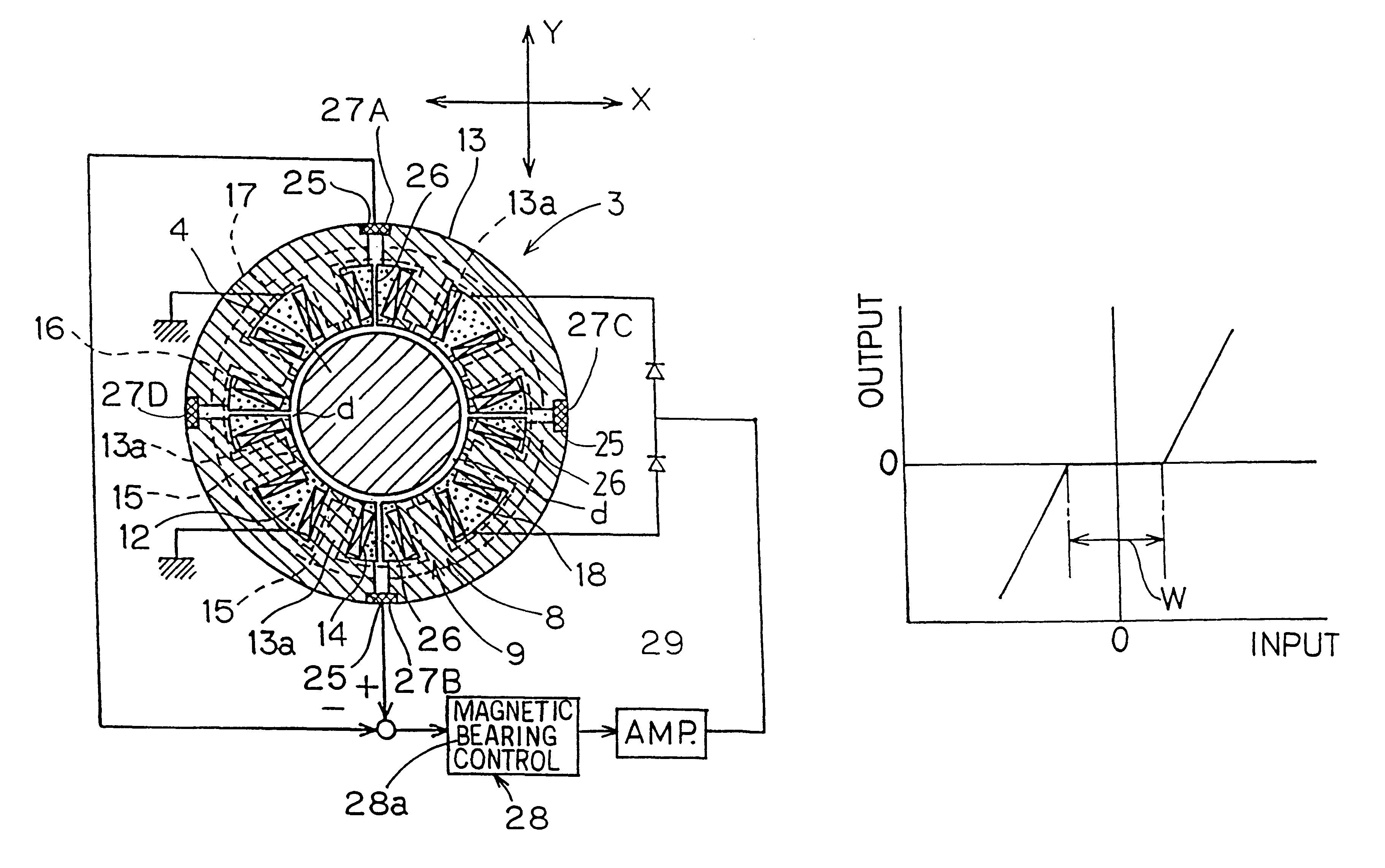
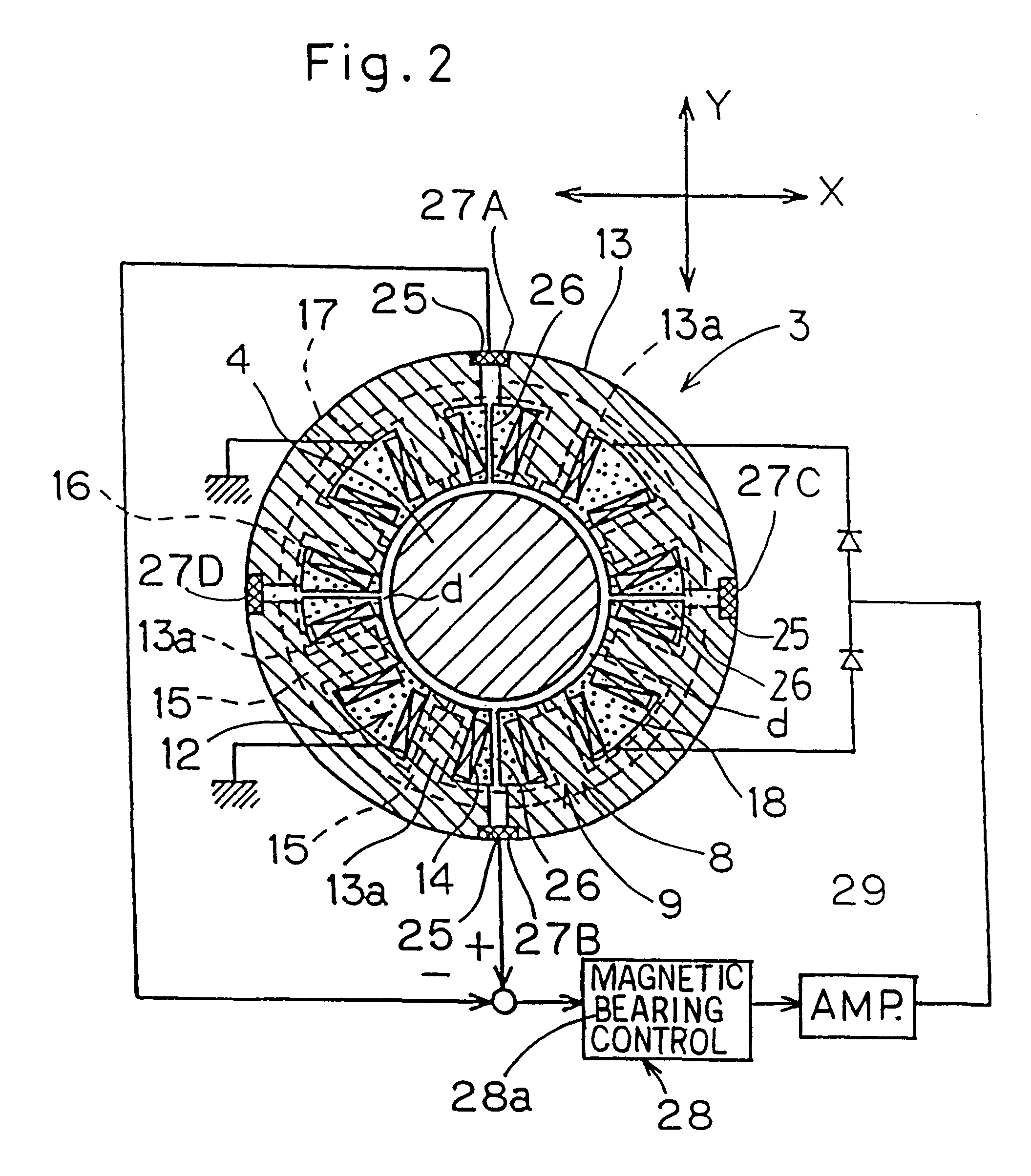
In addition, as is the case with the present invention as shown in FIG. 8, the pressure sensor 27 may be disposed directly within the inner diameter of the magnetic bearing 8, for example, within the core covering 18 or the like for measuring the pressure between the main shaft 4 and the core 13 so that the measured pressure can be converted into the displacement of the main shaft 4.

FIGS. 9 and 10 illustrate the combined externally pressurized gas and magnetic bearing assembly according to a third preferred embodiment of the present invention. In this embodiment, the combined externally pressurized gas and magnetic bearing assembly 3A of a type in which the orifices 15 for jetting a pressurized fluid medium into the bearing gap d of the externally pressurized gas bearing 9A are formed within the respective stator cores 13A of the radial magnetic bearing 8A makes use of the stator cores 13A of the electromagnets of the radial magnetic bearing 8 which are of a generally horseshoe shap...

fourth embodiment

FIGS. 11 to 13 illustrates the combined externally pressurized gas and magnetic bearing assembly 3B according to a fourth preferred embodiment of the present invention. According to this fourth embodiment of the present invention, in contrast to the example shown in FIGS. 9 and 10, the radial magnetic bearing 8A has stator cores of an improved shape. More specifically, of the yokes 13Ba and 13Bb of the cores 13B disposed axially of the main shaft 4, the yoke 13Ba is commonly shared by the circumferentially neighboring yoke to thereby simplify the structure. By so constructing the electromagnet, machining steps required to form the yokes 13B of the electromagnet can be reduced to thereby increase the machinability and, at the same time, the core loss at the main shaft portion of tile magnetic bearing which results from rotation of the main shaft 4 can be reduced to permit the main shaft 4 to be rotated at a high speed.

FIG. 14 illustrates a fifth preferred embodiment of the present in...

first embodiment

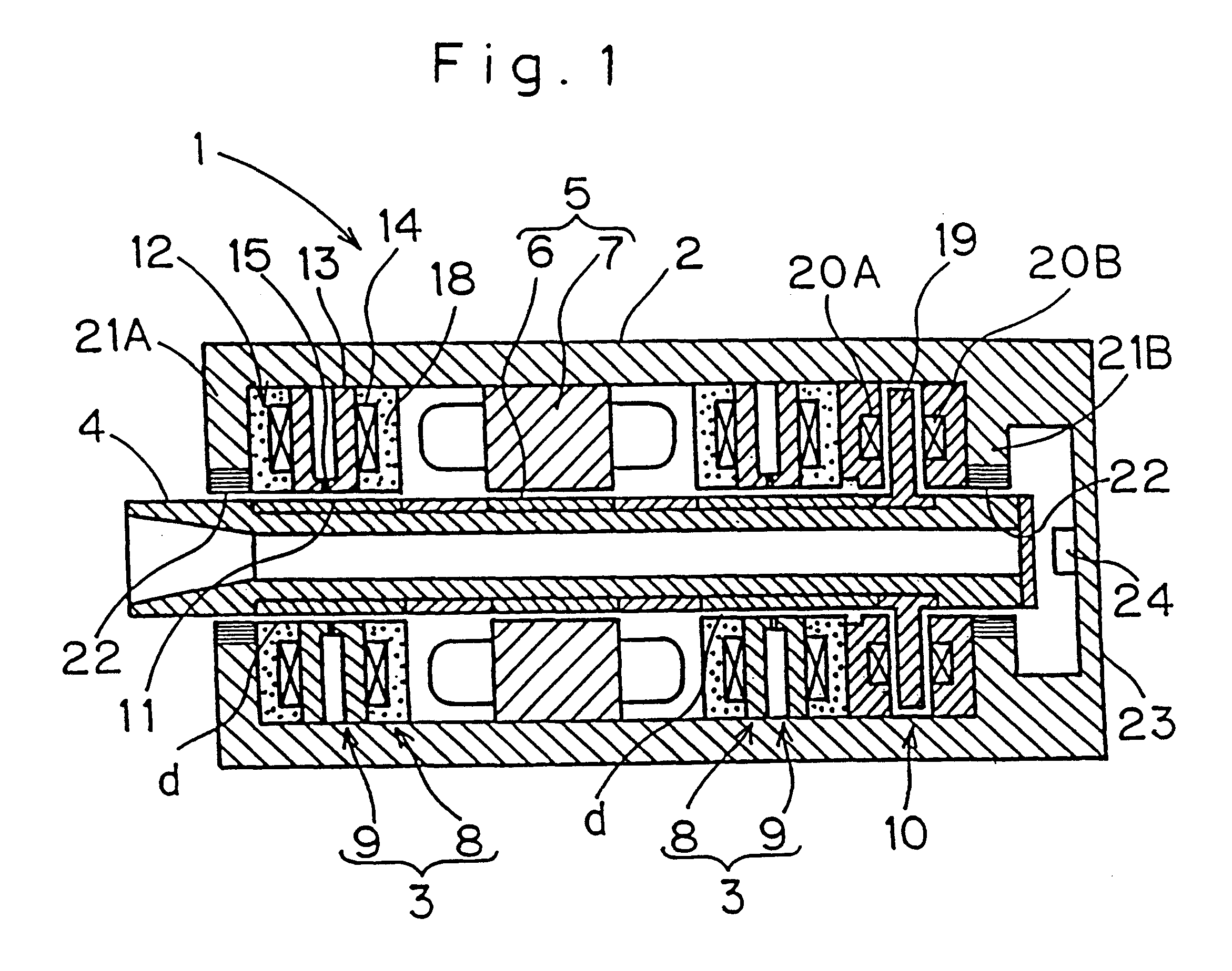
In the motor device used in the practice of the present invention shown in FIG. 1 where the drive motor 5 is designed to be of a type capable of providing a high output, the rotor 6 of the drive motor 5 would require both an increased wall thickness and an increased mass which would eventually result in reduction of the natural frequency of bending. However, in the embodiment of the present invention shown in FIG. 24, the problem associated with the possible reduction in natural frequency is eliminated by disposing the drive motor 5 at a location around a rear end portion of the main shaft 4.

An eleventh preferred embodiment of the present invention is shown in FIG. 25. The spindle device 1 embodying the combined externally pressurized gas and magnetic bearing assemblies is different from the spindle device 1 of FIG. 1 in that an eddy-current displacement sensor 30 is employed for each of the displacement sensors for detecting the radial displacement of the main shaft 4 relative to t...


PUM

PropertyMeasurementUnit
sizeaaaaaaaaaa
diameteraaaaaaaaaa
inner diameteraaaaaaaaaa

Abstract

A combined externally pressurized gas and magnetic bearing assembly (3) includes an externally pressurized gas bearing (9) and a magnetic bearing (8) that are integrated together so as to have component parts common to both of the externally pressurized gas bearing (9) and the magnetic bearing (8). The externally pressurized gas bearing (9) or the magnetic bearing (8) may be disposed within an axial extent of the magnetic bearing (8) or the externally pressurized gas bearing (9), respectively. A spindle device (1) utilizing the combined externally pressurized gas and magnetic bearing assembly (3) is also provided which includes a housing (2) for supporting a main shaft (4) rotatably through the combined externally pressurized gas and magnetic bearing assembly (3). This combined externally pressurized gas and magnetic bearing assembly (3) can be applied not only to the radial bearing, but also to the axial bearing.

Description

1. Field of the InventionThe present invention relates to a combined externally pressurized gas and magnetic bearing assembly in which an externally pressurized gas bearing and a magnetic bearing are combined together, and also to a spindle device employing the combined externally pressurized gas and magnetic bearing assembly. More particularly, the present invention relates to the combined externally pressurized gas and magnetic bearing assembly and the spindle device both suited for use in, for example, a high speed milling machine.2. Description of the Prior ArtThe magnetic bearing is known to have a feature in that because it has a relatively large bearing gap a loss of torque during rotation thereof is extremely small and it can exhibit a high static rigidity by an integral control.FIG. 28 illustrates a longitudinal sectional view showing a prior art spindle device utilizing a magnetic bearing, which is used in a high-speed aluminum milling machine. This prior art spindle devic...

Claims


Application Information

Patent Timeline
Patent Type & Authority Patents(United States)
IPC IPC(8): F16C39/06F16C32/06F16C32/00F16C39/00B23B19/02F16C32/04
CPCF16C32/00F16C32/0402F16C32/047F16C32/0603F16C32/0444F16C32/06Y10T409/309352
Inventor SUZUKI, NOBUYUKIYAMADA, HIROYUKI
Owner NTN CORP
Why Eureka
Try Eureka