Soft start compressor clutch

a compressor and clutch technology, applied in the field of clutches, can solve problems such as unsatisfactory noise, and achieve the effects of soft start, less objectionable noise and vibration, and reducing the objectionable characteristics of such a system

Inactive Publication Date: 2001-09-18
VISTEON GLOBAL TECH INC +1
View PDF6 Cites 90 Cited by
  • Summary
  • Abstract
  • Description
  • Claims
  • Application Information

AI Technical Summary

Benefits of technology

Accordingly, an object of the present invention is to provide, in an air conditioning compressor a clutch having a soft start which does not experience excessive wear.
An advantage of the use of a clutch according to the present invention is that the air conditioning system will have less objectionable noise and vibration. A second advantage is that, by reducing the objectionable characteristics of such a system, one may cycle the clutch more frequently and thereby maximize fuel efficiency and optimally control the temperature of the passenger compartment.
Further advantages include having the ability to operate the compressor at high speeds. With conventional clutches, operation at high engine RPMs causes undesirable noise. With a clutch according to the present invention, the clutch may be slipped, permitting lower RPM operation for a given input speed.
The present invention concerns an electromagnetic clutch for an air conditioning compressor housed in a compressor housing having a drive shaft extending from the housing and being rotatable about an axis of rotation. The clutch includes a generally cylindrical driving member having an axis of rotation and a peripheral annular first frictional

Problems solved by technology

With conventional clutches, operation at

Method used


Image

  • Soft start compressor clutch
  • Soft start compressor clutch
  • Soft start compressor clutch

Examples


Embodiment Construction

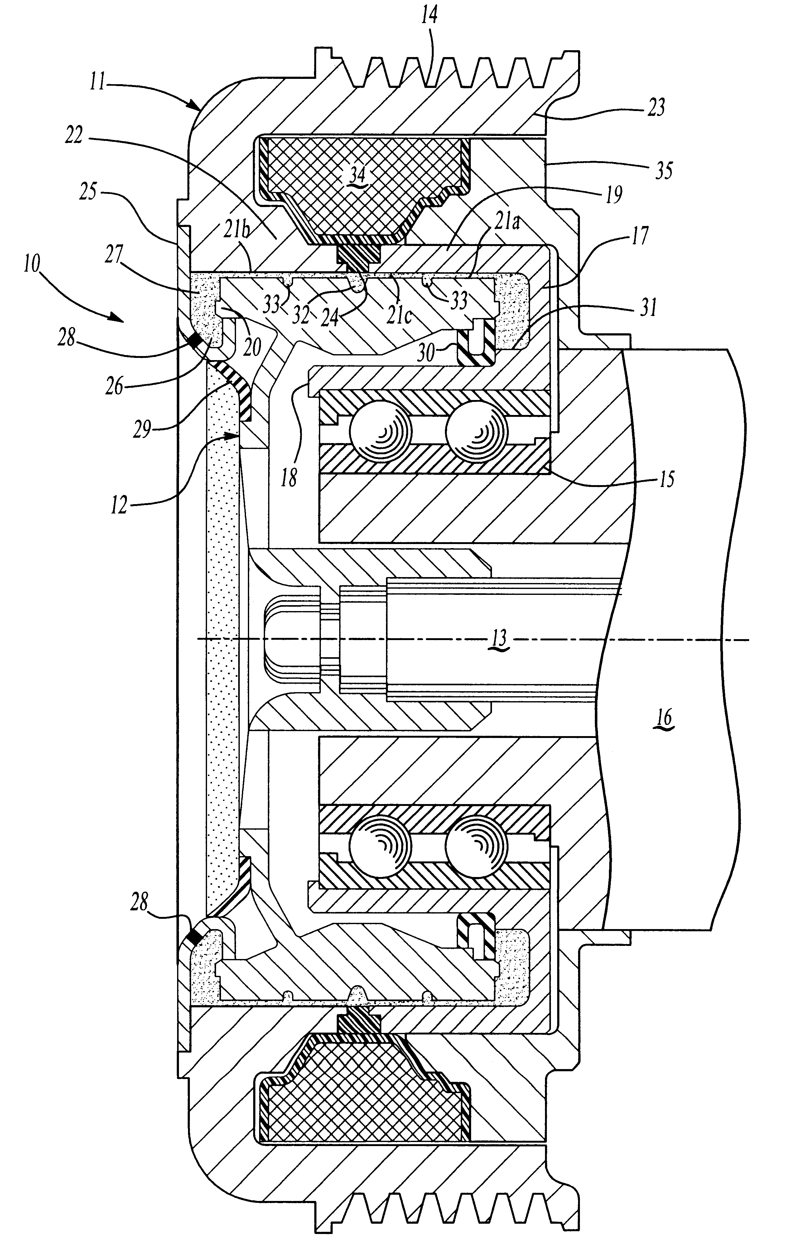
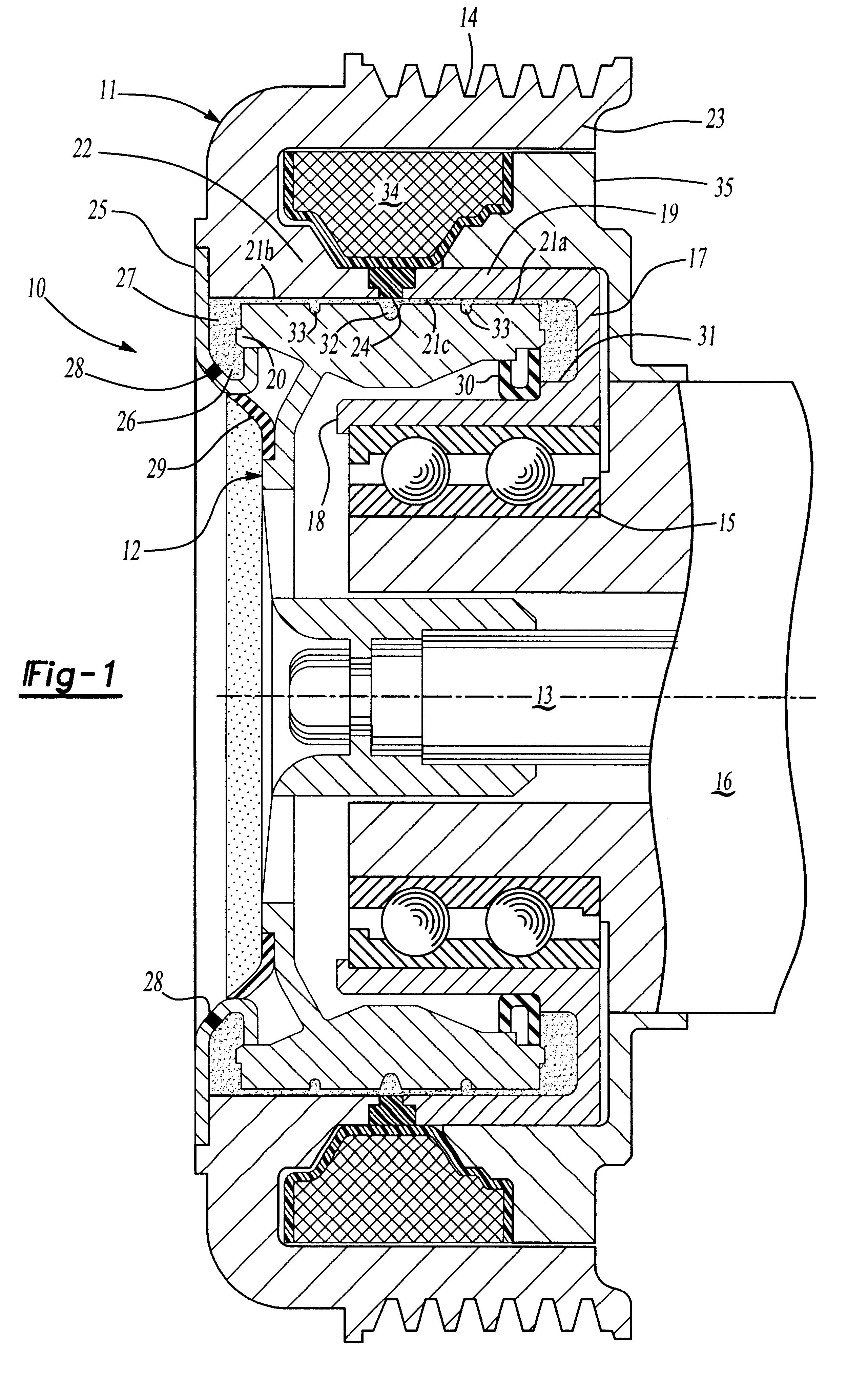
Referring first to FIG. 1, there is shown a clutch 10 for driving an air conditioning compressor (not shown) from an engine (not shown) in a motor vehicle (not shown). The clutch 10 includes a driving member 11 in the form of a pulley and a driven member 12 coupled to a shaft 13 of the compressor. The pulley 11 is driven by the vehicle engine through a belt (not shown) that engages V-grooves 14 formed in an exterior surface of the pulley in a known manner to provide rotation thereof while the vehicle engine is running. The clutch 10 allows the compressor to be selectively engaged with and disengaged from the pulley 11.

An annular bearing 15 is mounted on an axial extension of a housing 16 of the compressor. A ring shaped bearing mount 17 has an axially extending U-shaped cross section with an inner leg 18 supported on the bearing 15 and a generally parallel outer leg 19. The driven member 12 includes a peripheral flange 20 that extends axially between the legs 18 and 19 and has an ax...


PUM


Abstract

An electromagnetic clutch (10) for an air conditioning compressor includes a generally cylindrical pulley (11) rotatably mounted on a compressor housing (16) and having an annular friction surface (21b), a driven member (12) mounted on a compressor shaft (13) and having an annular friction surface (21a) positioned radially adjacent the first friction surface to form an annular space (21c) therebetween. A quantity of flowable magnetic material (27) is provided in the annular space (21c) and a magnetic coil (34) is fixed on the housing adjacent thereto. A control (40,46,46') connected to the magnetic coil (34) supplies electrical power from a power supply (47) to energize the magnetic coil and create magnetic flux in the annular space (21c) polarizing the magnetic material and frictionally coupling the first and second friction surfaces (21a,21b) to cause the pulley (11) to rotate the driven member (12). The control (40,46,46') can pulse width modulate or ramp the supplied power for "soft" starting and/or stopping of the compressor.

Description

BACKGROUND OF THE INVENTION1. Technical FieldThis invention relates to the field of clutches for a compressor in an air conditioning system. More particularly, the invention pertains to such a clutch having soft start characteristics.2. Description of the Prior ArtA compressor for an air conditioning system of an automobile typically includes a clutch to enable disengagement of the compressor during periods in which no air conditioning is desired. During demand situations, the clutch is engaged so that the compressor compresses the refrigerant in a known manner. Prior art clutches typically are of an electromagnetic friction clutch construction. A compressor typically is driven by a V-groove pulley assembly supported by a bearing pressed onto the body of the compressor. The pulley is driven by the automotive accessory drive belt.Prior art clutches typically include an armature affixed to the splined shaft of the compressor via a bolt. A stationary wire coil assembly is press-fit to ...

Claims


Application Information

Patent Timeline
IPC IPC(8): F16D37/02F16D37/00
CPCF16D37/02F16D2037/002
Inventor GINDER, JOHN M.ELIE, LARRY D.HARTE, SHANE A.KHETARPAL, VIPENCOHEN, ALEX DAVID
Owner VISTEON GLOBAL TECH INC
Why Eureka
Try Eureka