Redundant memory cell for dynamic random access memories having twisted bit line architectures

a dynamic random access memory and memory cell technology, applied in the field of redundant rows of memory cells, can solve the problems of increasing circuitry overhead, complicated decoding of reference cells rows, and limited use of redundant rows

Inactive Publication Date: 2001-09-18
STMICROELECTRONICS SRL
View PDF1 Cites 29 Cited by
  • Summary
  • Abstract
  • Description
  • Claims
  • Application Information

AI Technical Summary

Problems solved by technology

As can be seen, the decoding of rows of reference cells is more complicated in DRAM devices having a twisted bit line architecture.
This approach, however, disadvantageously results in an increase in circuitry overhead and a limited use of the redundant rows, hence poorer efficiency.

Method used


Image

  • Redundant memory cell for dynamic random access memories having twisted bit line architectures
  • Redundant memory cell for dynamic random access memories having twisted bit line architectures
  • Redundant memory cell for dynamic random access memories having twisted bit line architectures

Examples


Embodiment Construction

The present invention will now be described more fully hereinafter with reference to the accompanying drawings in which a preferred embodiment of the invention is shown.

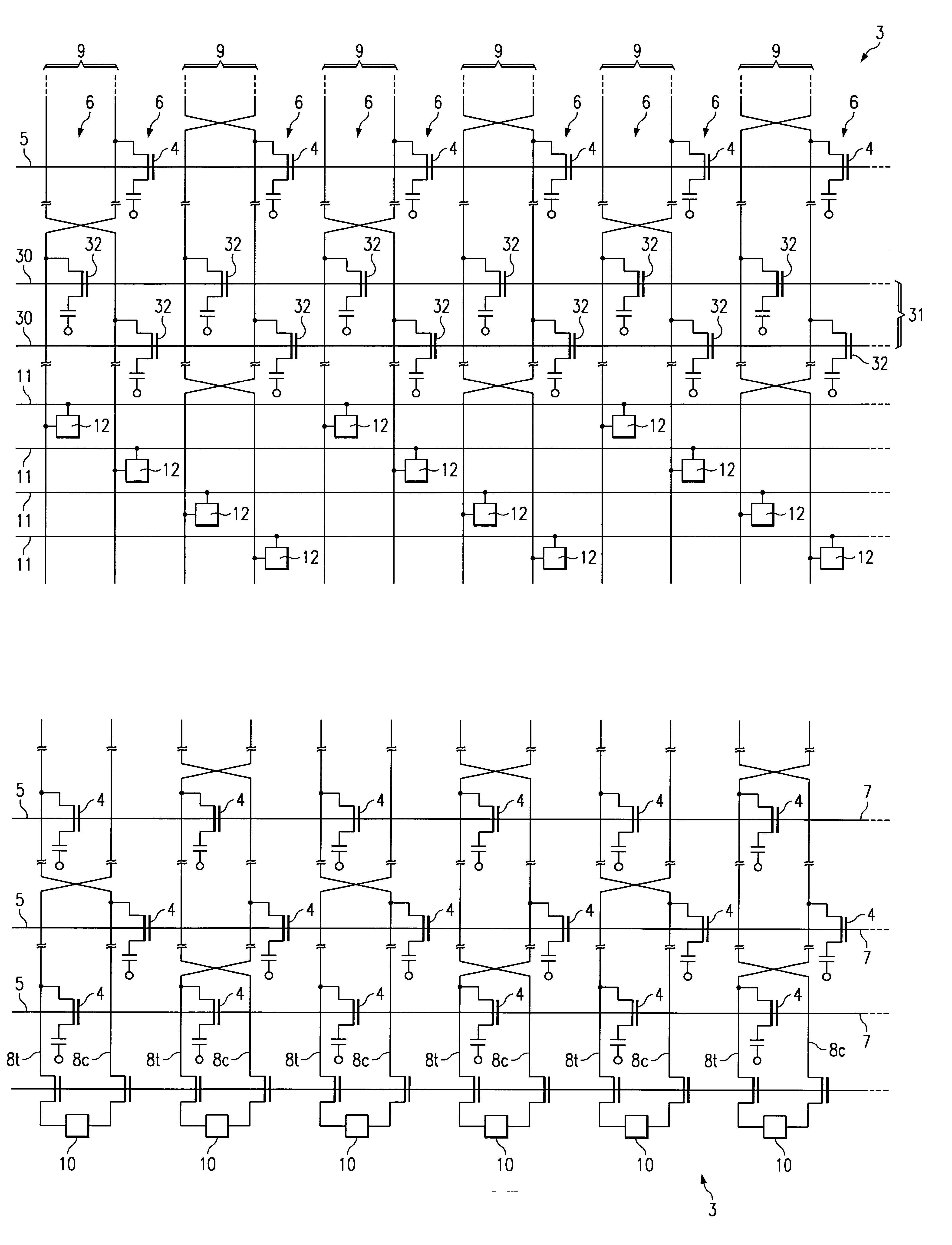
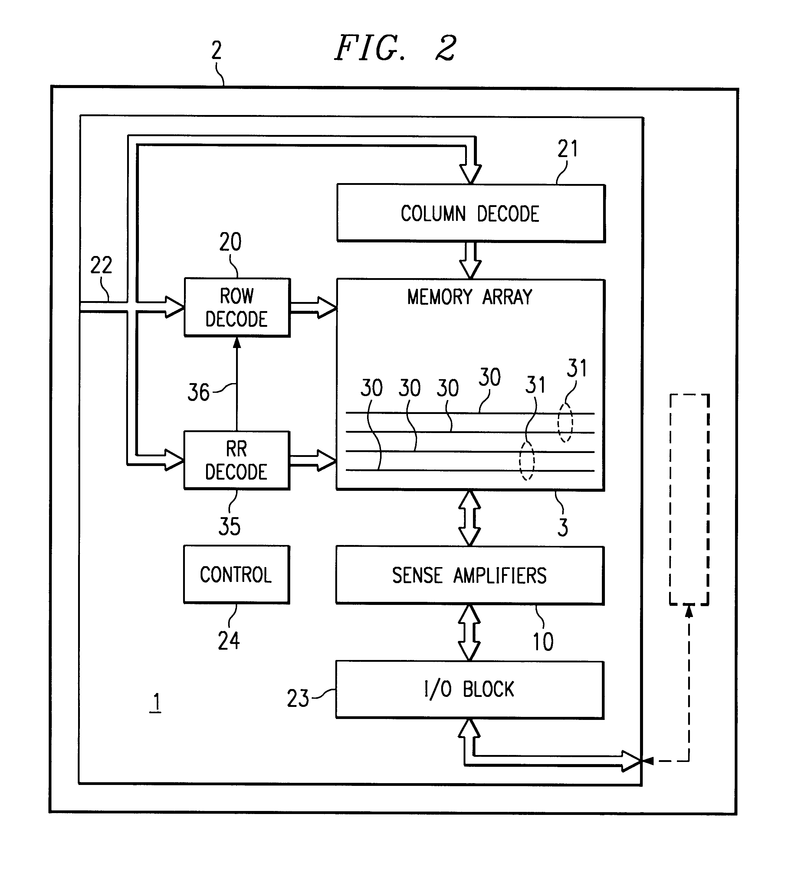
Referring to FIGS. 2-3, there is shown a dynamic random access memory (DRAM) device 1 according to a preferred embodiment of the present invention. DRAM device 1 may form part or all of an integrated circuit 2. For example, DRAM device 1 may be a stand-alone, off-the-shelf memory device 2. Alternatively, DRAM device 1 may be an embedded memory within integrated circuit 2 that also includes application specific circuitry (shown in dashed lines) so as to form an application specific integrated circuit (ASIC).

DRAM device 1 includes a memory cell array 3 having memory cells 4 organized into a plurality of rows 5 and columns 6 (FIG. 3). Each row 5 of memory cells 4 is coupled to a distinct word line 7, and each column 6 of memory cells 4 is coupled to a distinct bit line 8. A row of memory cells 4 is activated and connect...


PUM


Abstract

A dynamic random access memory (DRAM) device is disclosed. The DRAM device includes a memory cell array having a twisted bit line architecture. The memory cell array includes at least one pair of redundant rows of memory cells. Redundant row decode circuitry is capable of configuring the pair of redundant rows to replace any one row of memory cells having a defect. Each pair of bit lines is coupled to a distinct memory cell from each redundant row of the redundant row pair so that both the true and complement version of a data value is maintained by the redundant row pair. Rows of reference cells are disconnected and/or disabled during a memory access operation involving the redundant row pair. The use of a pair of redundant rows of memory cells to replace a single row of memory cells having a defect substantially reduces the complexity of decode circuitry for enabling the rows of reference cells.

Description

1. Technical Field of the InventionThe present invention relates to redundant rows of memory cells for dynamic random access memory (DRAM) devices, and particularly to the use of redundant rows of memory cells for DRAM devices having a twisted bit line architecture.2. Background of the InventionA conventional DRAM device includes an array of memory cells organized into rows and columns. Each row of memory cells is coupled to an individual word line, and each column of memory cells is coupled to an individual bit line. The array further includes rows of reference cells which cooperate with a selected row of memory cells to place a charge differential on each pair of bit lines during a memory access operation for determining the data values stored in the memory cells.In particular, a reference cell and a memory cell from an addressed row are connected to a bit line pair during a memory access operation and present a charge differential thereon to be sensed. The memory cell is then ref...

Claims


Application Information

Patent Timeline
Patent Type & Authority Patents(United States)
IPC IPC(8): G11C7/18G11C7/00G11C11/409G11C5/06G11C11/4097G11C11/401G11C29/04
CPCG11C5/063G11C11/4097G11C7/18
Inventor WORLEY, JAMES L.
Owner STMICROELECTRONICS SRL
Why Eureka
Try Eureka