
Reconfigurable optical filtering apparatus and a drop-and-insert multiplexer incorporating such apparatus

a technology of optical filtering apparatus and multiplexer, which is applied in the direction of electromagnetic repeaters, transmission monitoring, instruments, etc., can solve the problems of unoptimized complexity and cost, and achieve the effect of reducing the number of waveguides and the number of gates accordingly

Inactive Publication Date: 2001-09-18
ALCATEL LUCENT SAS
View PDF4 Cites 5 Cited by
  • Summary
  • Abstract
  • Description
  • Claims
  • Application Information

AI Technical Summary

Benefits of technology

To this end, the invention provides optical filtering apparatus including n stop filters set to different wavelengths or to different combs of wavelengths, and optical switching means having a plurality of states and suitable for coupling an input optical signal to any one of said filters or to a plurality of said filters selectively coupled in cascade, wherein said switching means are provided with n+l inlet ports of ranks 0 to n, and n+1 outlet ports of ranks 1 to n+1, as well as a set of waveguides making it possible to couple each outlet port selectively to one of said inlet ports of lower rank, wherein, with each of said filters being provided with first and second opposite ports, the first port and the second port of each filter are coupled respectively to an associated outlet port and to an associated inlet port of the same rank of said switching means, and wherein the inlet port of rank 0 is organized to receive said input optical signal, and the outlet port of rank n+1 is organized to deliver an output optical signal.
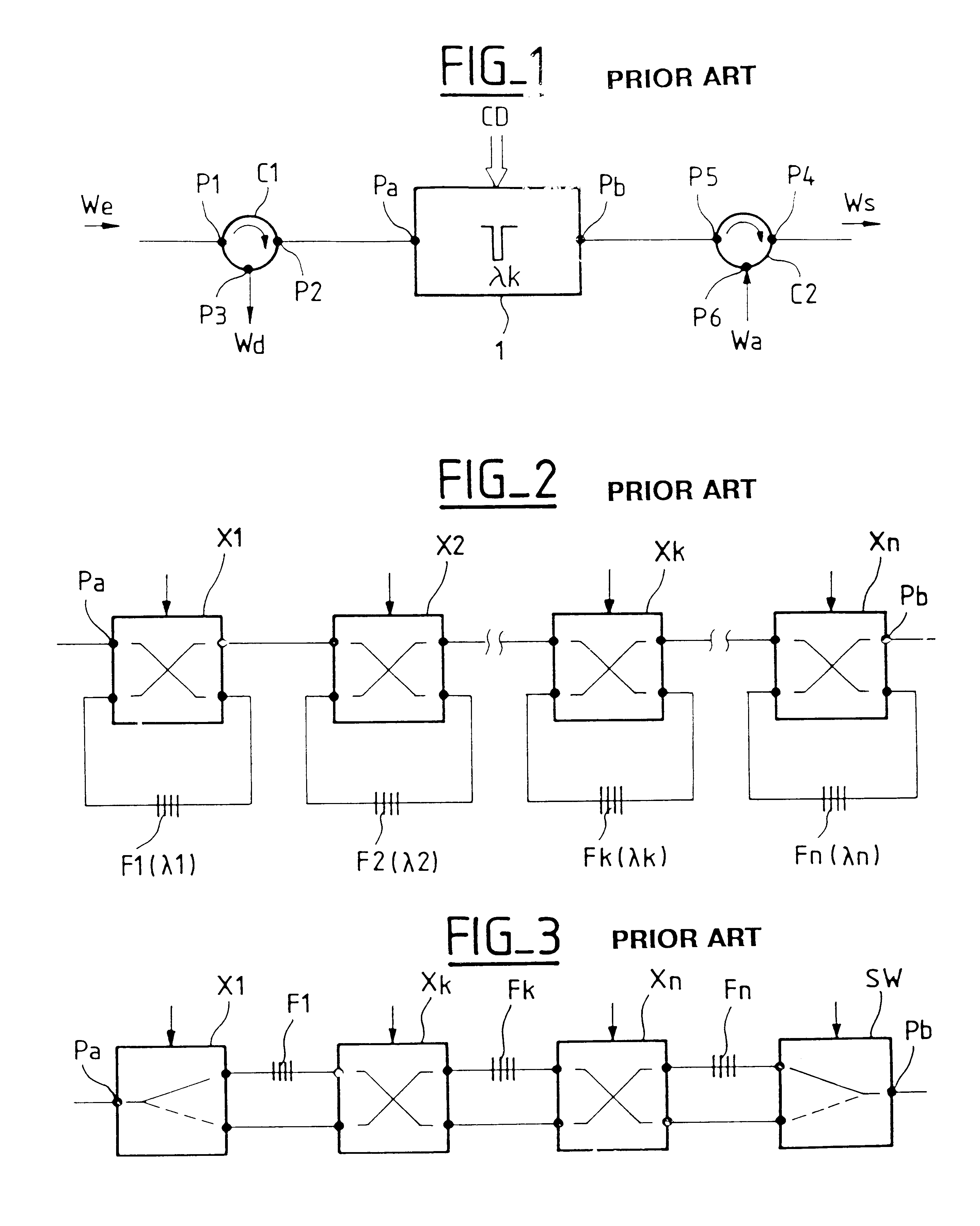
Thus, with a usual static crossbar switch constituted by n+1 1-to-(n+1) couplers interconnected with n+1 (n+1)-to-1 couplers via waveguides provided with controlled optical gates, the number of waveguides used is in fact only (n+1)(n+2) / 2. It is thus possible to reduce the number of waveguides and the number of gates accordingly.

Problems solved by technology

However, such a solution is not optimum as regards complexity and cost.

Method used


Image

  • Reconfigurable optical filtering apparatus and a drop-and-insert multiplexer incorporating such apparatus
  • Reconfigurable optical filtering apparatus and a drop-and-insert multiplexer incorporating such apparatus
  • Reconfigurable optical filtering apparatus and a drop-and-insert multiplexer incorporating such apparatus

Examples


Embodiment Construction

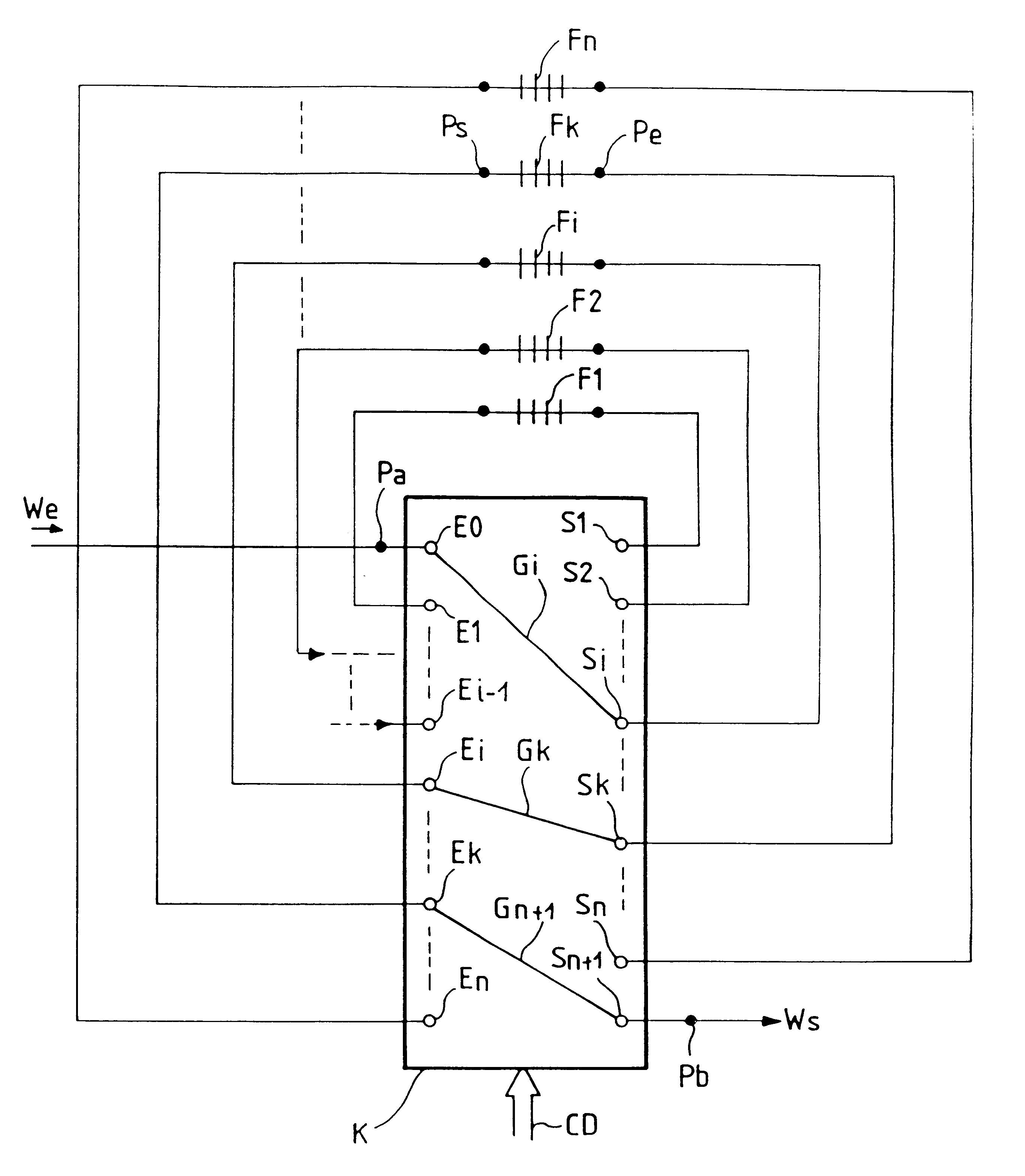
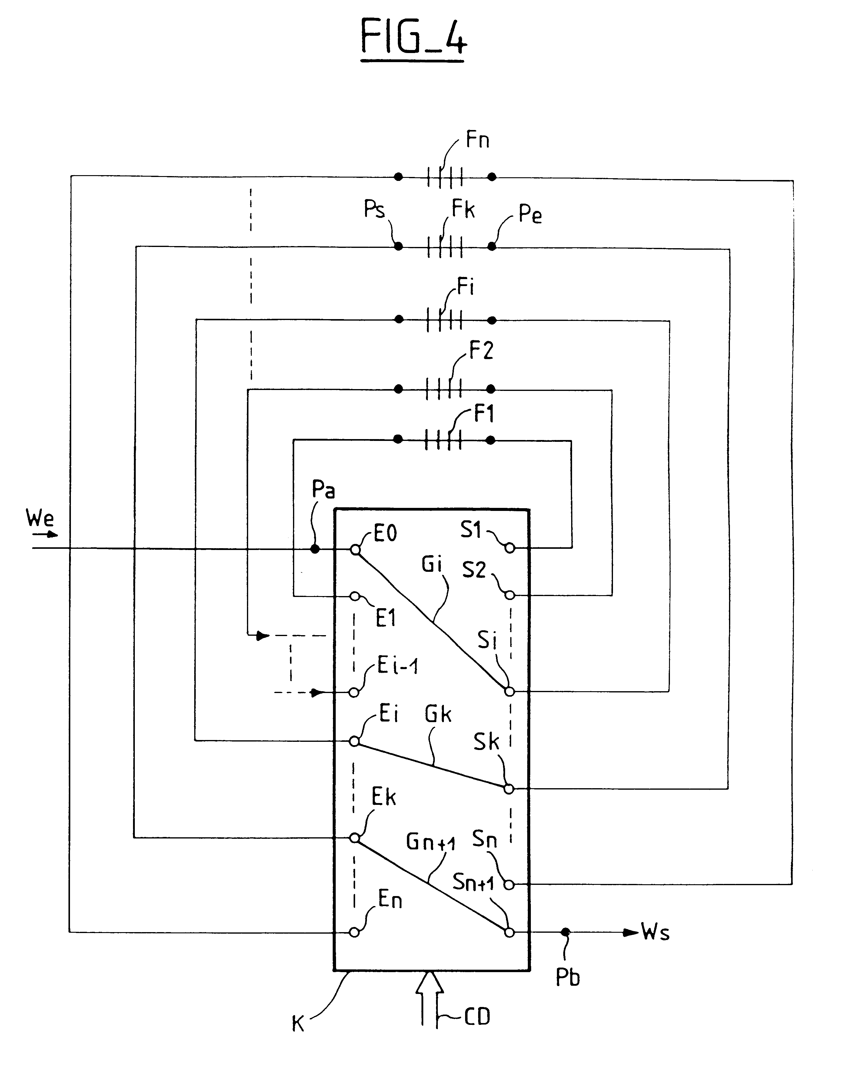
The filter shown in FIG. 4 is constituted by an optical switch K and by n stop filters Fl, F2, Fi, Fk, Fn. Each filter is organized to stop (and to reflect for drop-and-insert applications) one or more channels of a received wavelength division multiplex We.

The switch K is provided with n+1 outlet ports of ranks 1 to n: EO, El, Ei, Ek, En, and n+1 outlet ports of ranks 1 to n+1: S1, S2, Si, Sk, Sn+1.

Each of the filters, e.g. Fk, is provided with first and second opposite ports Pe, Ps coupled respectively to an outlet port Sk and to an inlet port Ek of the same rank of the switch K.

A set of waveguides of the switch K, such as Gi, Gk, Gn+1, activated as a function of a suitable command CD, makes it possible selectively to couple each outlet port, e.g. Sk, to one of the inlet ports, e.g. Ei, having a lower rank.

The first inlet port E0, of rank 0, is organized to receive the input multiplex signal We and the last outlet port Sn+1, of rank n+1, is organized to deliver an output optical s...


PUM


Abstract

In particular for selectively dropping and / or inserting channels of a wavelength division multiplex, while minimizing losses, the apparatus includes n stop filters and optical switching means provided with n+1 inlet ports of ranks 0 to n, and n+1 outlet ports of ranks 1 to n+1, as well as a set of waveguides making it possible to couple each outlet port selectively to one of said inlet ports of lower rank. Each filter is provided with first and second opposite ports coupled respectively to an associated outlet port and to an associated inlet port of the same rank. Application to optical transmission, in particular for performing routing operations.

Description

The invention lies in the field of optical transmission using wavelength division multiplexing (WDM). It relates to wavelength filtering apparatus and more particularly to reconfigurable filters for selectively removing one or more channels of the multiplex. The invention also relates to apparatus that makes it possible selectively to drop and / or to insert at least some of said channels. Such apparatus may commonly be referred to as a"drop-and-insert" multiplexer and may advantageously use such reconfigurable filters.In WDM transmission systems, a plurality of channels are conveyed simultaneously over the same fiber, each of the channels being carried by an associated wave having a determined center wavelength and a determined bandwidth. In particular, for performing routing or switching functions, it is often necessary to drop certain channels and to modify the multiplex, e.g. so as to modify the information conveyed by one or more channels, or so as to replace the wavelength carry...

Claims


Application Information

Patent Timeline
IPC IPC(8): G02B6/34H04J14/02H04Q11/00G02B6/293H04B10/27H04B10/2507H04B10/29H04B10/296
CPCG02B6/2932G02B6/29383G02B6/29395H04Q11/0001H04J14/0212H04J14/0219H04J14/0209
Inventor BISSON, ARNAUDBRUYERE, FRANCKNOIRIE, LUDOVIC
Owner ALCATEL LUCENT SAS
Learn More