Thread joint percussive drilling equipment

a percussive drilling and thread joint technology, applied in the direction of hose connection, screws, borehole/well accessories, etc., can solve the problems of female threads damaging each other and the lifespan of the joint becoming relatively short, and achieve the effect of prolonging the tool li

Inactive Publication Date: 2001-09-25
SANDVIK INTELLECTUAL PROPERTY AB
View PDF10 Cites 38 Cited by
  • Summary
  • Abstract
  • Description
  • Claims
  • Application Information

AI Technical Summary

Benefits of technology

One object of the present invention is to provide a thread joint of the above-indicated type in which a longer tool life is attained.

Problems solved by technology

The sharp edges result in the male and female threads damaging each other foremost at the free end of the respective drilling element during mounting and dismounting of the joint.
Results from the hardening show cracking and fatigue in these areas during drilling, and therefore the lifespan of the joint becomes relatively short.

Method used


Image

  • Thread joint percussive drilling equipment
  • Thread joint percussive drilling equipment
  • Thread joint percussive drilling equipment

Examples


Embodiment Construction

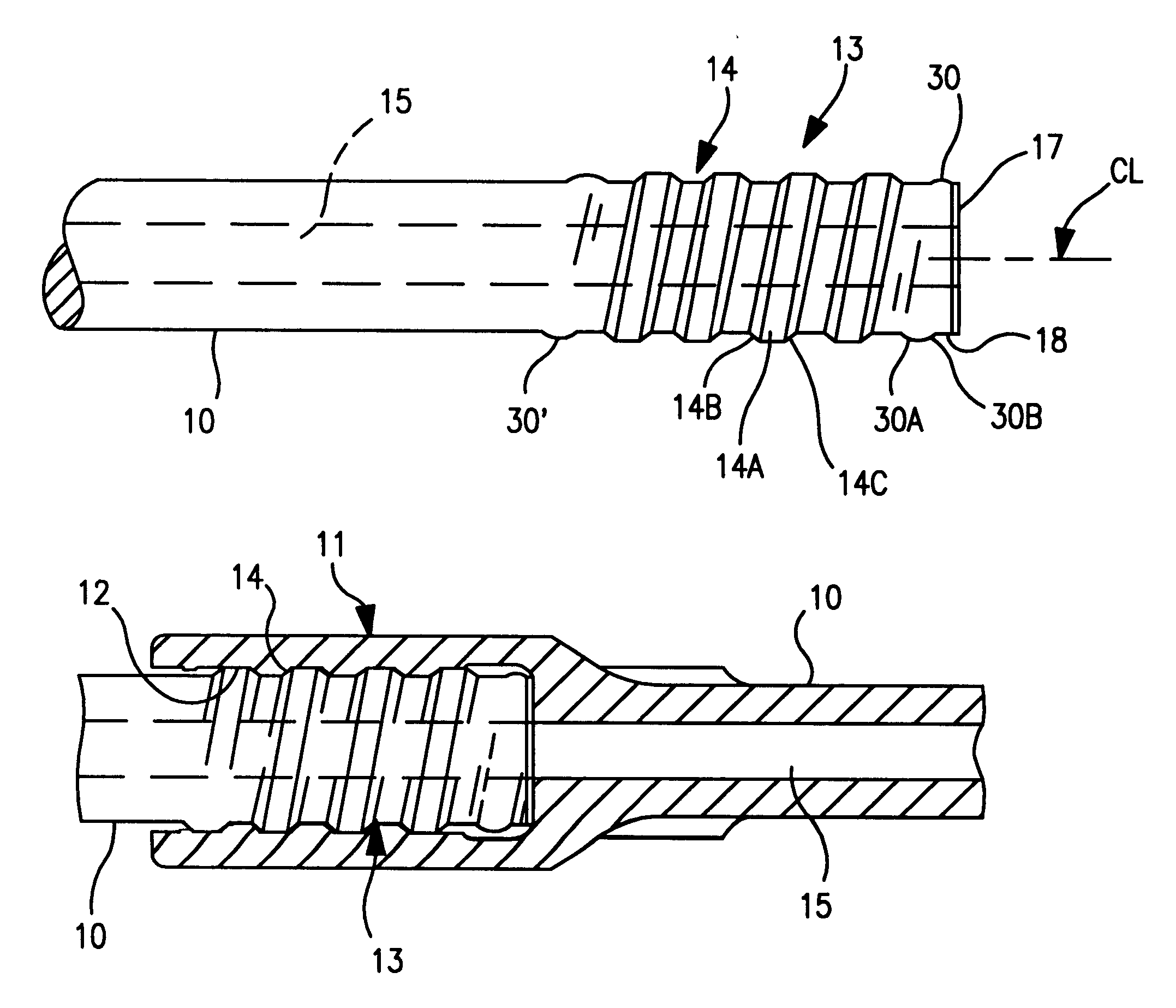
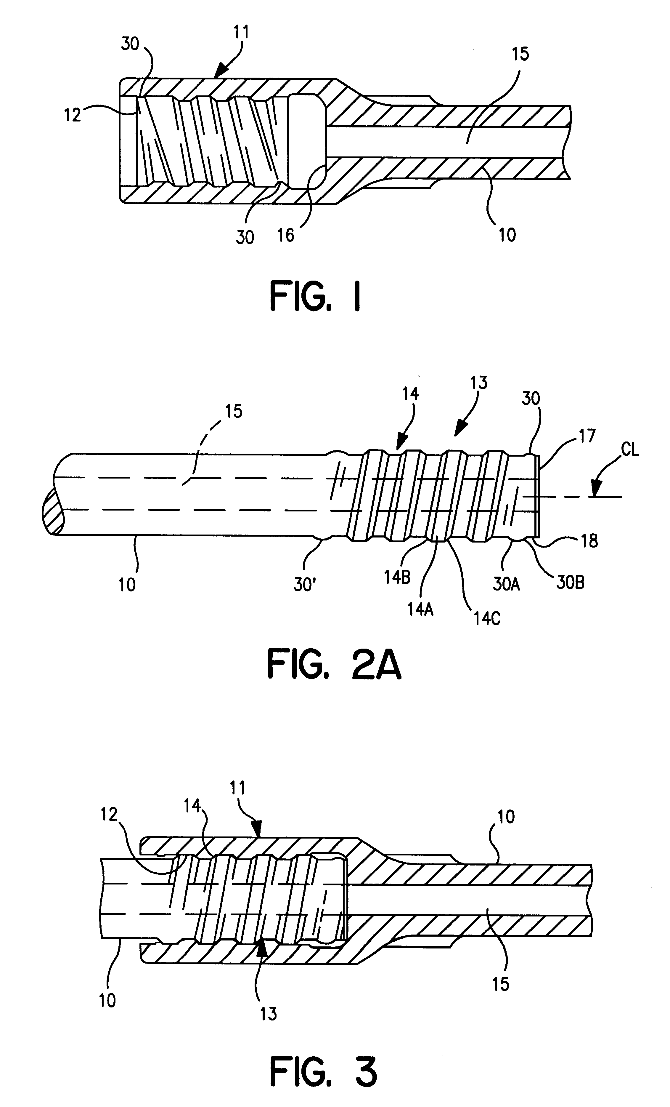
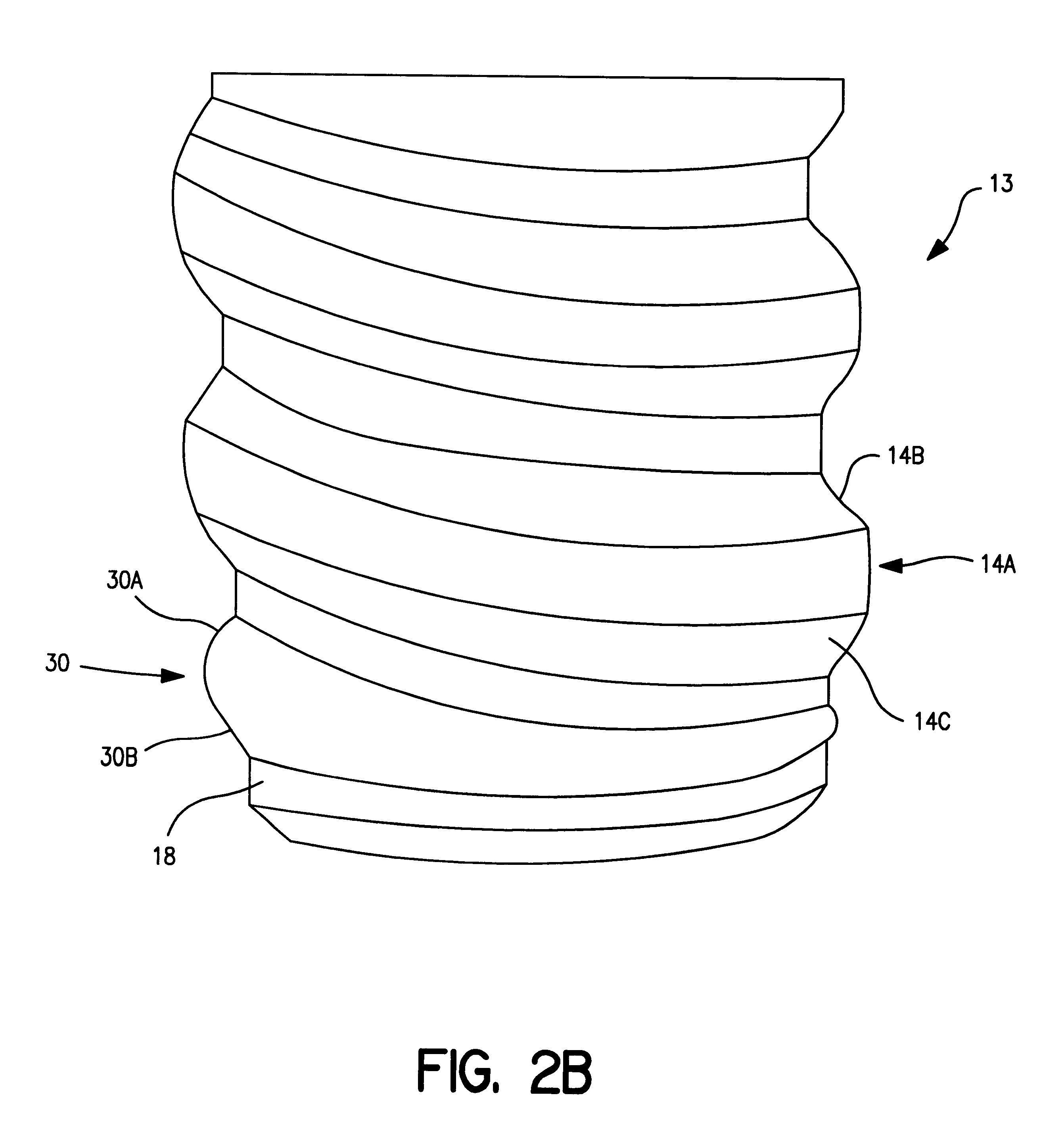
The drill rod 10 for percussive drilling shown in FIGS. 1, 2A and 2B is provided at one end with a sleeve-shaped part or a female portion 11 having a female thread or internal thread 12 according to the present invention. The female portion 11 constitutes an integral part of the drill rod 10. At the other end the drill rod 10 is formed with a spigot or male portion 13 equipped with a male thread or external thread 14 according to the present invention. The drill rod further has a through-going flush channel 15, through which a flush medium, generally air or water, is conducted. The female portion 11 bottom forms a ring-shaped abutment surface 16, which when mounting two drill rods 10 is intended to abut against a corresponding annular abutment surface 17 disposed at the free end of the shank 13 of the other drill rod.

In FIGS. 4 and 5A-5D there are shown an end view of the male portion and different longitudinal cross-sections of an entrance end section 30 of the thread, as well as a...


PUM


Abstract

A thread joint for percussive drilling equipment includes first and second percussive drill string components, the first component including a spigot. An external thread is formed on the spigot, and an internal thread is formed on the second component. Each of the internal and external threads includes an end section gradually transforming into a full thread section. The end section includes a pair of flanks, and the full thread section also includes a pair of flanks. Both flanks of the end section have a different profile than the corresponding flanks of the full thread section.

Description

The present invention relates to a thread joint, a male portion, a female portion and a method for manufacturing a thread product for use in percussive drilling equipment.PRIOR ARTIn a conventional thread joint between two components in a rock drilling equipment for percussive drilling, one normally uses male and female threads that have been formed by cutting, see for example Swedish Patent No. 469,602 corresponds to (U.S. Pat. No. 4,687,368). At manufacturing of such a male thread a blank of steel is formed, which comprises a thick part having ends that connect to a clearance surface or a clearance groove of less diameter to receive at least portions of the threading tool and to an often conical free end. Subsequently, the tool's lateral and longitudinal feed are coordinated with the rotational movement of the thick portion such as to generate the thread in a conventional manner during at least one pass. Sharp edges are formed at the entrance and exit ends of the thread due to the...

Claims


Application Information

Patent Timeline
Patent Type & Authority Patents(United States)
IPC IPC(8): E21B17/042E21B17/02
CPCE21B17/0426
Inventor LILJEBRAND, PER-OLOFOLSSON, URBAN
Owner SANDVIK INTELLECTUAL PROPERTY AB
Why Eureka
Try Eureka