Luminous intensity detection and control system for slit lamps and slit lamp projections

a technology of slit lamps and control systems, which is applied in the field of luminous intensity detection and control systems for slit lamps and slit lamp projections, can solve the problems of short-term overstrain of the eye to be examined, and the inability to prevent short-term overstrain of the eye under examination as a result of an excessively high light load

Inactive Publication Date: 2001-10-09
G RODENSTOCK INSTR
View PDF1 Cites 28 Cited by
  • Summary
  • Abstract
  • Description
  • Claims
  • Application Information

AI Technical Summary

Problems solved by technology

In such an approach short-term overstrain on the eye to be examined cannot be precluded.
Even though the presently applied methods and means for determining and influencing the luminous intensity on slit lamps and

Method used


Image

  • Luminous intensity detection and control system for slit lamps and slit lamp projections
  • Luminous intensity detection and control system for slit lamps and slit lamp projections
  • Luminous intensity detection and control system for slit lamps and slit lamp projections

Examples


Embodiment Construction

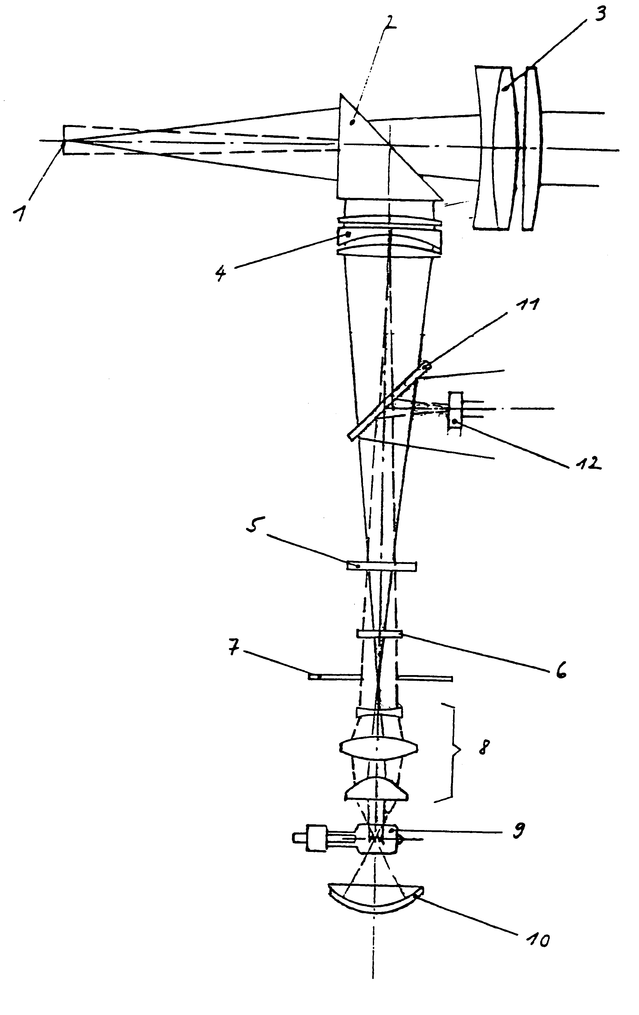
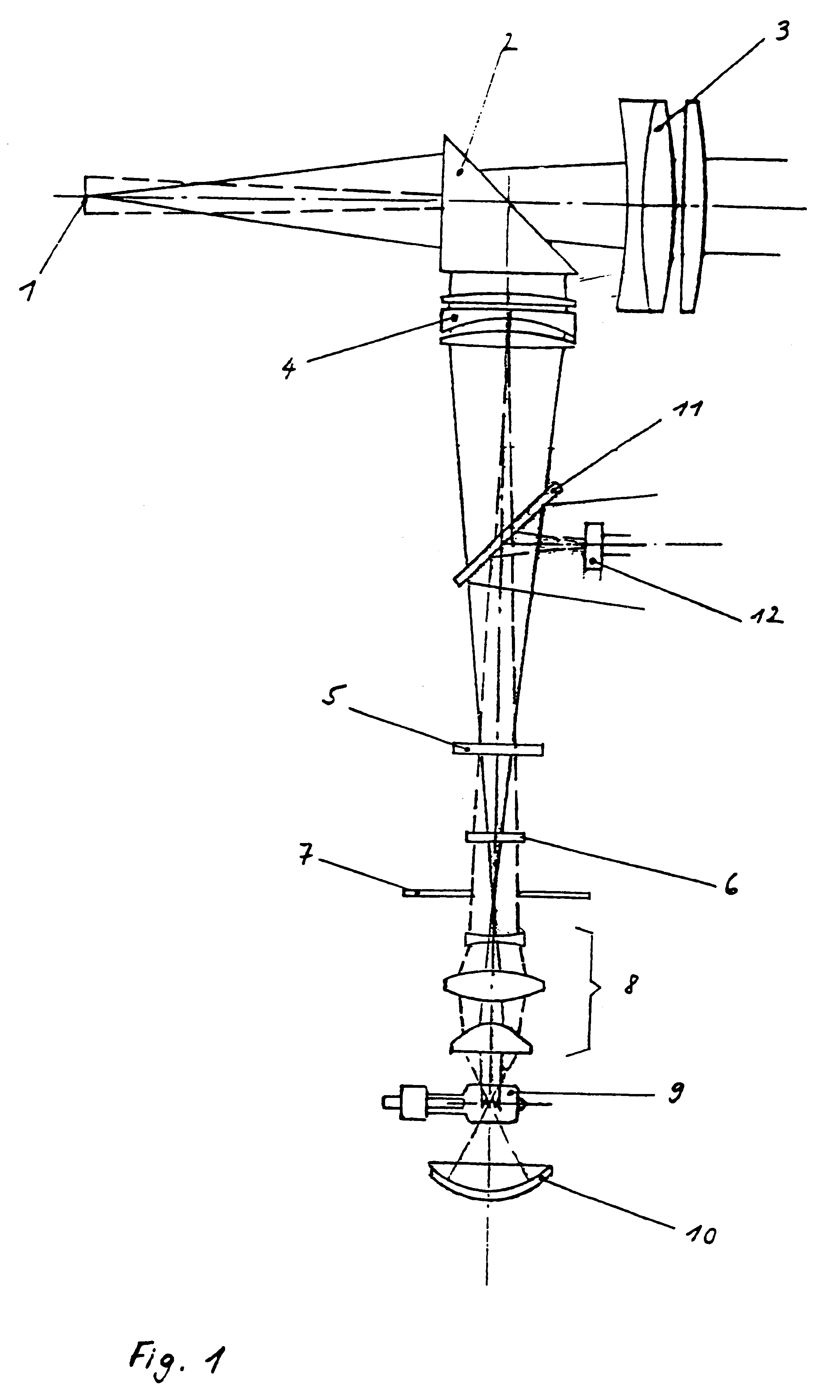
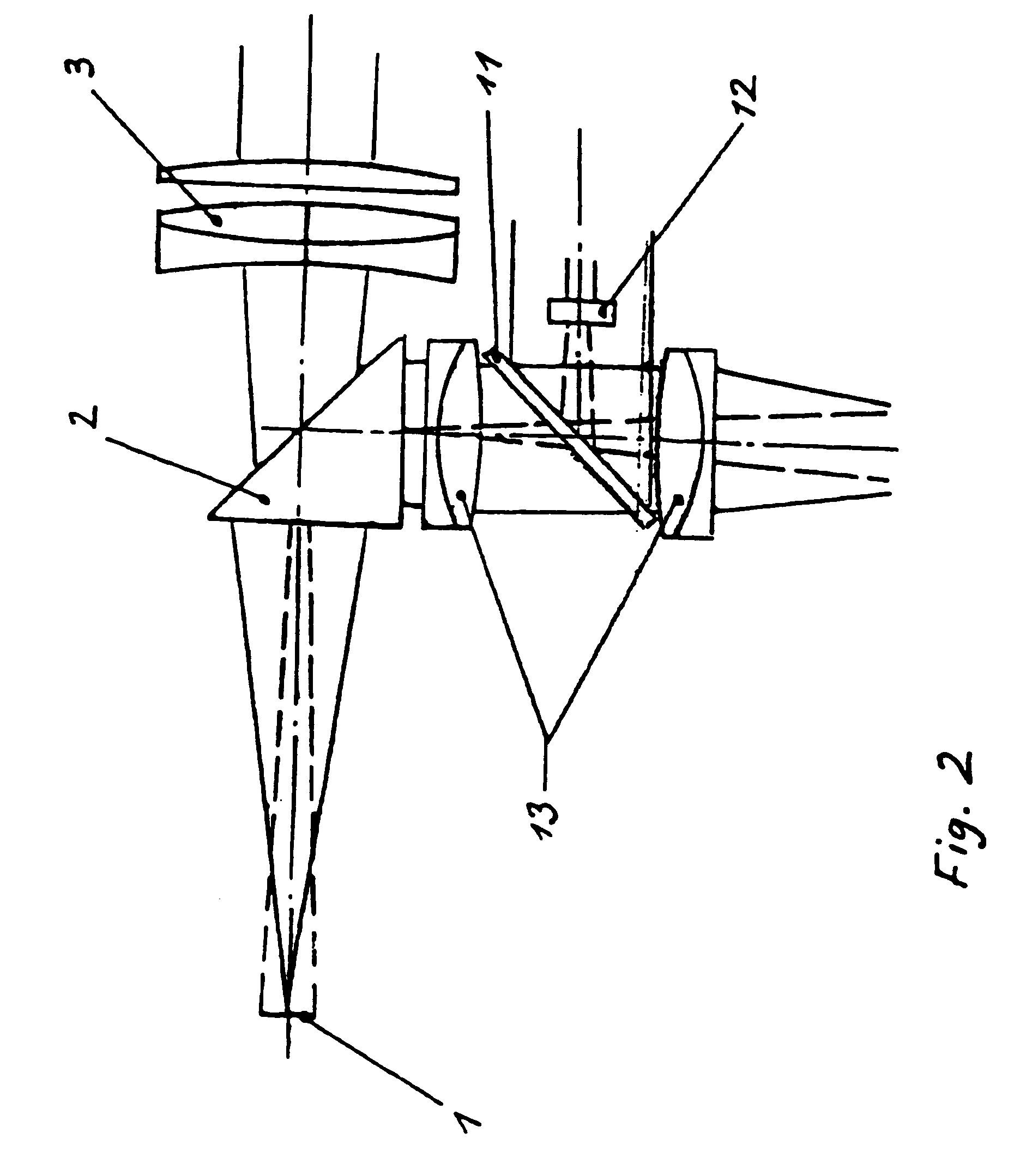
FIG. 1 shows a slit lamp in an embodiment comprising a "slit projector" lens 4. In this model the slit image 1, a reflecting prism 2, the stereo microscope lens 3, the slit projector lens 4, the filter assembly consisting of a colour neutral glass filter 5 and UV absorption filter 6, the slit diaphragm 7, a condenser 8 with IR absorption features, a halogen lamp 9 and a concave mirror 10 are arranged in a manner common for such a configuration. In accordance with the present invention an oblique thin glass flat 11 with a total reflection of 2 percent approximately is disposed in a slit lamp or a slit lamp projector of this kind at an angle of 45 degrees relative to the optical path above the filter assembly consisting of the colour neutral glass filter 5 and the UV absorption filter 6 between the latter and the "slit projector" lens 4. Thus one part of the incident rays is directed as deflected light cone to a detector 12 or a detector assembly, respectively, which is laterally disp...


PUM


Abstract

The invention is characterised by the provision that in a slit lamp or a slit lamp projector an oblique thin glass flat with a partial reflection of the light is disposed at a defined angle relative to the optical path above the filter assembly between the latter and the "slit projector" lens (4), and in the configuration with an achromatic doublet lens between the lens assemblies in the parallel optical path, in such a way that as a result one part of the incident rays is incident as deflected light cone on a detector assembly which is arranged laterally in the housing at an angle dependent on the angle of the thin glass flat in the housing, which detector assembly measures the respectively existing luminous intensity, transmits the detected values to an evaluation and control means which compares the values so received against a predetermined maximum value, calculates the irradiation dose for the phakic or aphakic eye and, when the value is exceeded, signals this situation on an indicating alarm means and/or reduces the luminous intensity automatically to the predetermined maximum value in a controlled manner.

Description

The present invention relates to a luminous intensity detection and control system for slit lamps and slit lamp projectors.PRIOR ARTSlit lamps or slit lamp projectors have become known which consist of a microscope and a pivotable illuminating system, which generates a slit image. They serve the purpose of an enlarged observation of the eye and its environment. Inter alia such solutions have become known in which the optical system of the slit image projector is, so to speak, an improvement of the slit image projects so far common. There the attempt was made for the first time to merge the optical condenser system with the optical lens system so as to form a highly efficient unit. The condenser serves the purpose of projecting the image of the bulb filament onto the lens or the exit prism, respectively. It is the function of the lens of the lamp to project the slit and iris diaphragm into the axis of rotation of the device, i.e. onto the eye. Furthermore, these devices comprise the ...

Claims


Application Information

Patent Timeline
IPC IPC(8): A61B3/13A61B3/135
CPCA61B3/135
Inventor REIS, WERNER
Owner G RODENSTOCK INSTR
Why Eureka
Try Eureka