Device for supporting a receptacle in a cantilevered-out position

a technology of cantilevering and receptacle, which is applied in the direction of packaging goods, liquid bottling, additives, etc., can solve the problems of reducing productivity, reducing the degree of automation, so as to achieve the effect of limiting the exten

Inactive Publication Date: 2001-10-16
SERAC GROUP
View PDF8 Cites 45 Cited by
  • Summary
  • Abstract
  • Description
  • Claims
  • Application Information

AI Technical Summary

Benefits of technology

An object of the invention is to provide a device for supporting a receptacle in a cantilevered-out position, while limiting the extent to which the rec

Problems solved by technology

Unfortunately, the maximum filling flow rate and thus the transverse dimensions of the jet of filling substance are determined relative to the real cross-section of the neck.
There therefore exists a risk that the filling substance will flow outside the receptacle while the platform is rotating.
However that reduces productivity.
It is then more difficult to put the receptacle into place in the clamp and to re

Method used


Image

  • Device for supporting a receptacle in a cantilevered-out position
  • Device for supporting a receptacle in a cantilevered-out position
  • Device for supporting a receptacle in a cantilevered-out position

Examples


Embodiment Construction

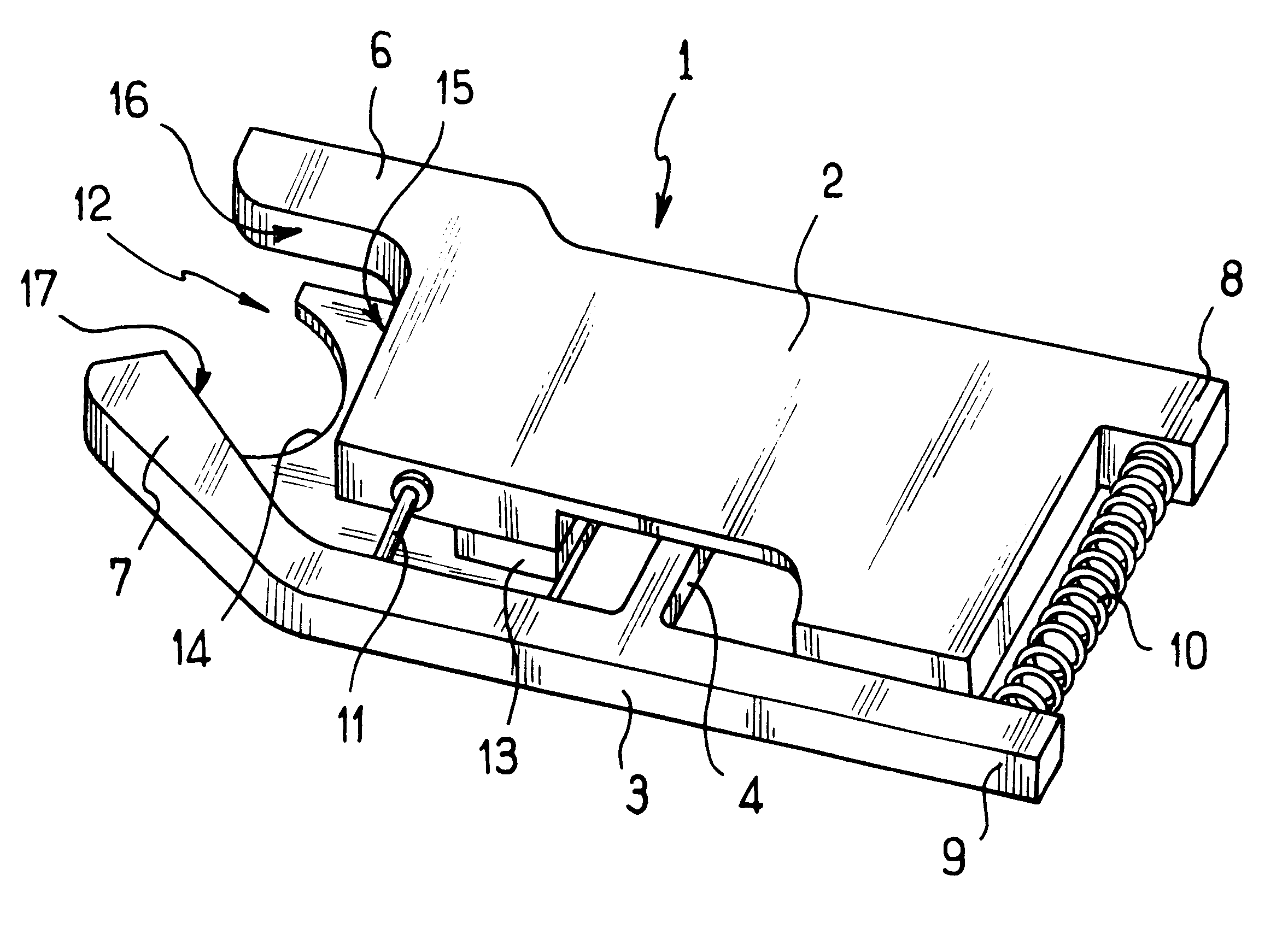
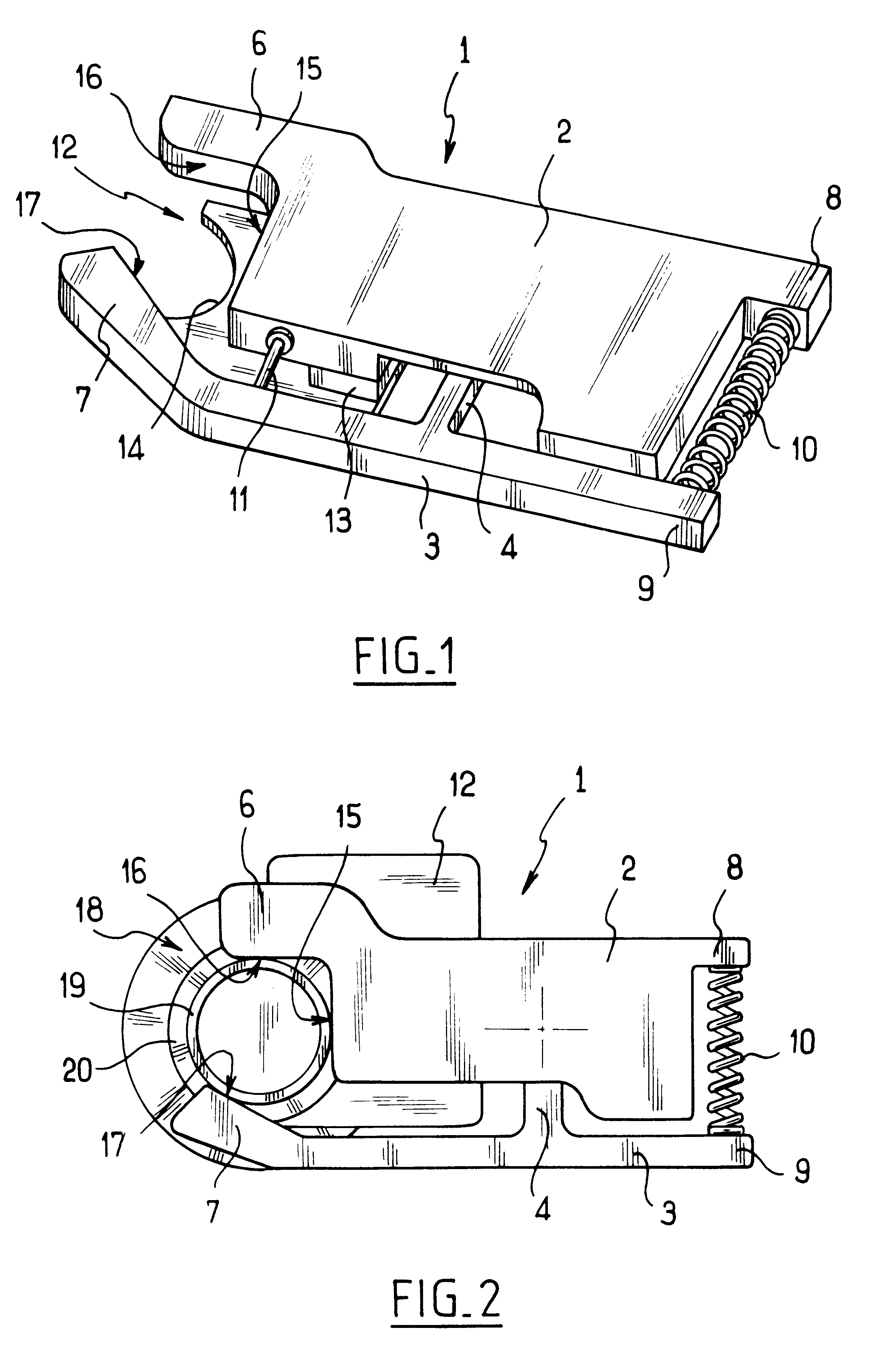
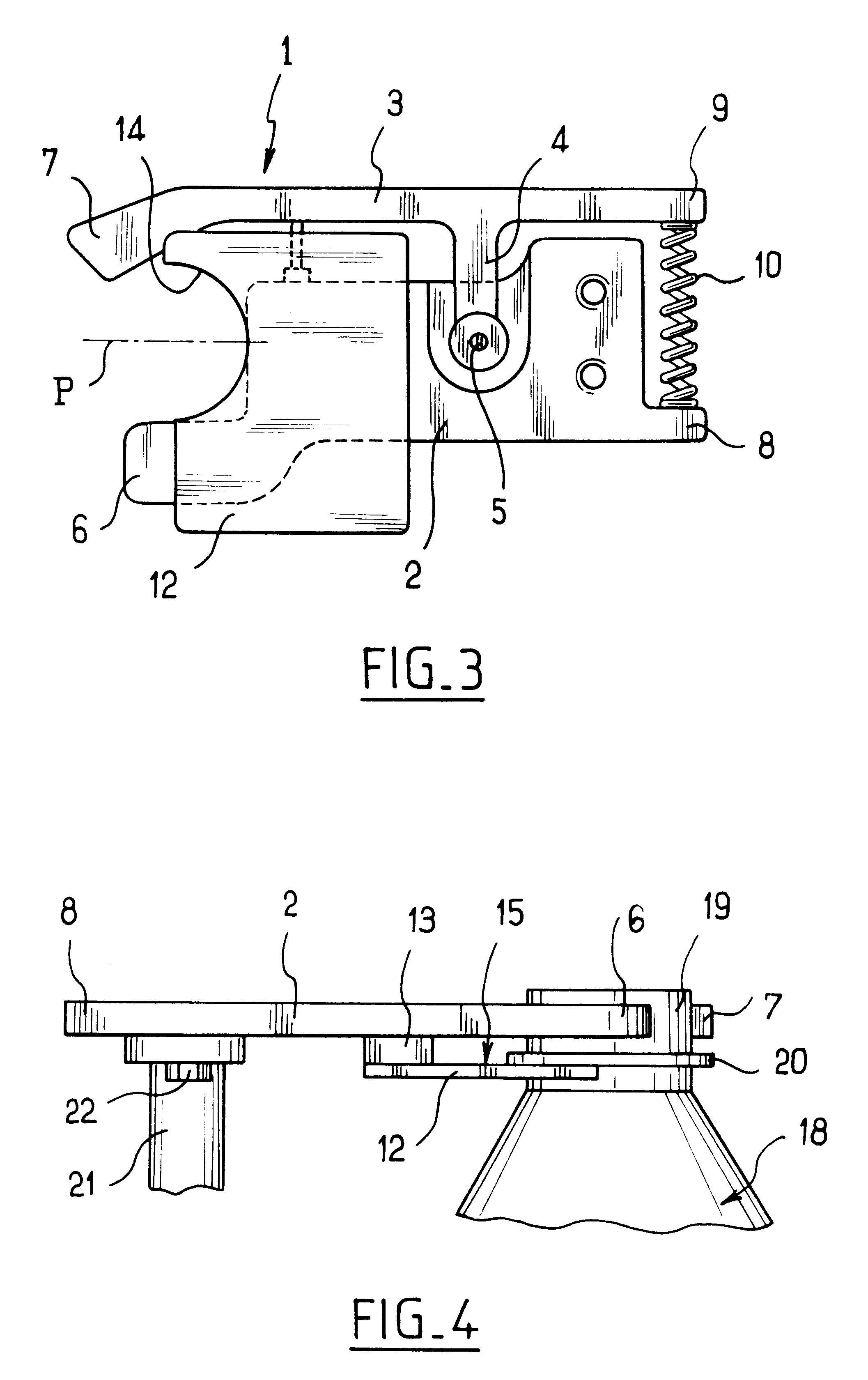
The support device described below is designed to support receptacles 18 in a cantilevered-out position, each receptacle having a cylindrical neck 19 and a collar 20 extending around the neck 19.

The support device of the invention comprises a clamp given overall reference 1, and having a first limb 2 and a second limb 3. The second limb 3 comprises a link arm 4 extending laterally relative to the limb 3 and having one end mounted to pivot on the limb 2 about a hinge axis 5.

The limbs 2 and 3 have facing ends forming respective jaws 6 and 7. At their ends remote from the jaws 6 and 7, the limbs 2 and 3 have ends 8 and 9 between which there extends a spring 10 to exert force tending to move the jaws 6 and 7 towards each other. An adjustable abutment finger 11 secured to the limb 3 between the jaw 7 and the link arm 4 has a free end bearing against the limb 2 in order to limit closure of the clamp.

The support device also has a support element given overall reference 12 and constituted b...


PUM

PropertyMeasurementUnit
Dimensionaaaaaaaaaa
Symmetryaaaaaaaaaa

Abstract

A support device for supporting, in a cantilevered-out position, a receptacle having a neck that includes a collar, the device comprising a resiliently-closable clamp having first and second hinged-together jaws, and a rigid support element presenting a lateral opening forming a housing for a portion of the neck and a support for the collar of the receptacle, the support element extending beneath the clamp and being spaced apart therefrom.

Description

The present invention relates to a device for supporting, in a cantilevered-out position, a receptacle having a neck including a collar. The device is suitable for use in particular in installations for filling receptacles.In general, a device for supporting a receptacle in a cantilevered-out position comprises a resiliently closable clamp having two jaws hinged to each other and urged towards a closed position by a return spring. One of the jaws has means for enabling the device to be fixed to an installation such as a rotary filling platform.On a platform of that type, the clamp of the support device holds the neck of the receptacle so as to suspend the receptacle beneath a filling spout.While the platform is rotating, the receptacle tends to tilt under the action of centrifugal force. The projected cross-section thus presented by the neck of the receptacle beneath the filling spout is elliptical in shape and smaller than the real cross-section of the neck which is circular. Unfor...

Claims


Application Information

Patent Timeline
IPC IPC(8): B67C3/02B67C3/24
CPCB67C3/242C10M163/00C10M133/56C10M137/10C10M149/22C10M159/22C10M159/24C10M167/00C10M143/00C10M145/14C10M145/16C10M145/36C10M149/04C10M149/06C10M149/10
Inventor DE VILLELE, DAMIEN
Owner SERAC GROUP
Why Eureka
Try Eureka