Connecting a plurality of circuit boards

a technology of circuit boards and circuit boards, applied in the direction of circuit optical details, optical elements, instruments, etc., can solve the problems of high clock frequency, prohibitive cost of fabricating prior art circuits, etc., and achieve the effect of reducing the cost of conventional electronic solutions and reducing the cost of fabrication

Inactive Publication Date: 2001-10-16
LUMENTUM TECH UK LTD
View PDF18 Cites 66 Cited by
  • Summary
  • Abstract
  • Description
  • Claims
  • Application Information

AI Technical Summary

Benefits of technology

wherein the optical circuit comprises one or more integrated optical circuits providing:

Problems solved by technology

Pin Counts, high clock frequencies and electromagnetic interference (EMI) make this problematic.
Such optical interconnects are discussed in the literature, e.g. BT Technol J Vol 9 No 4 1991, but all the work in this field has so far employed discrete optical components and the costs of fabricating prior art circuits has so far been prohibitive compared to the cost of the conventional electronic solution.

Method used


Image

  • Connecting a plurality of circuit boards
  • Connecting a plurality of circuit boards
  • Connecting a plurality of circuit boards

Examples


Embodiment Construction

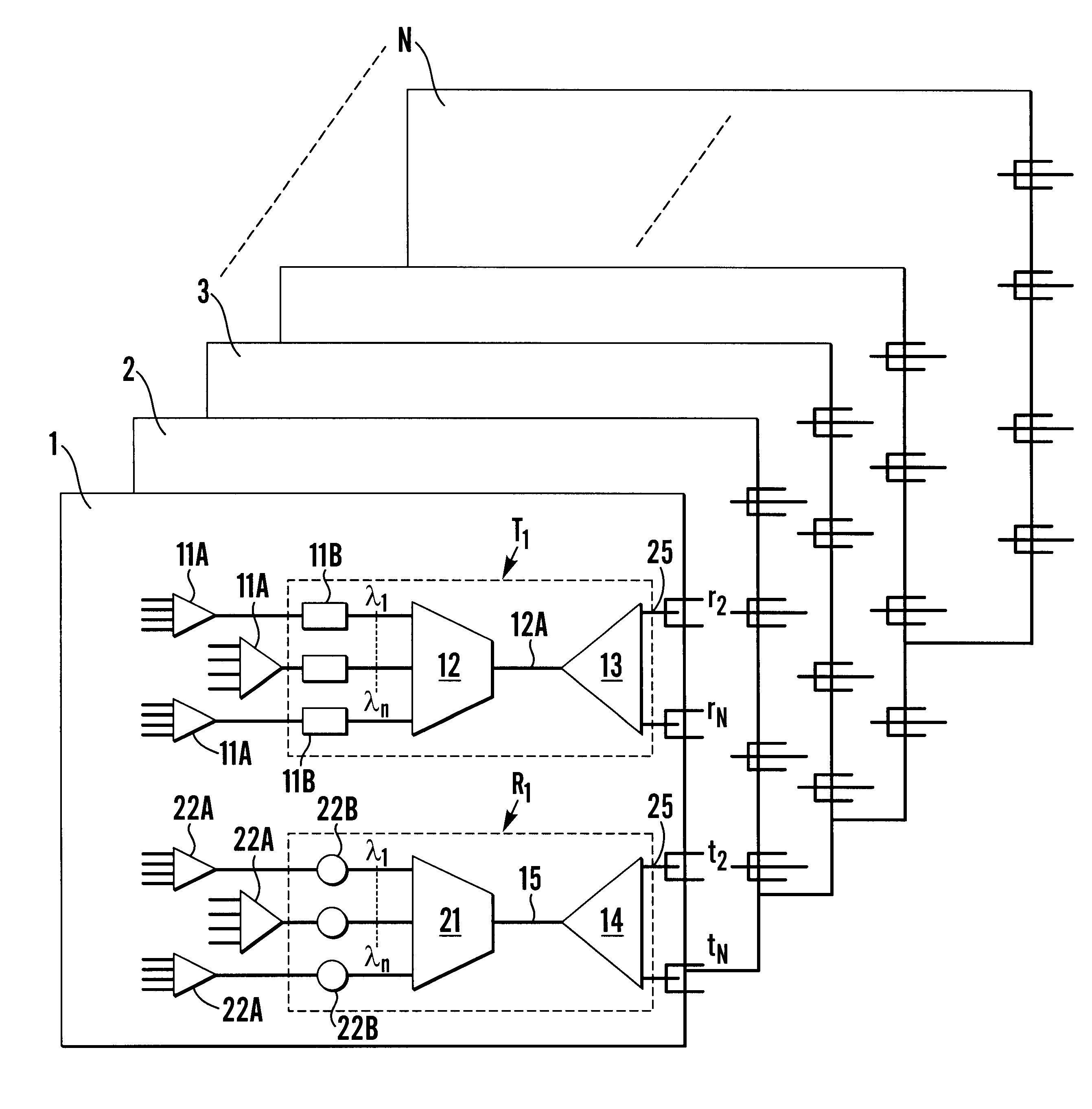
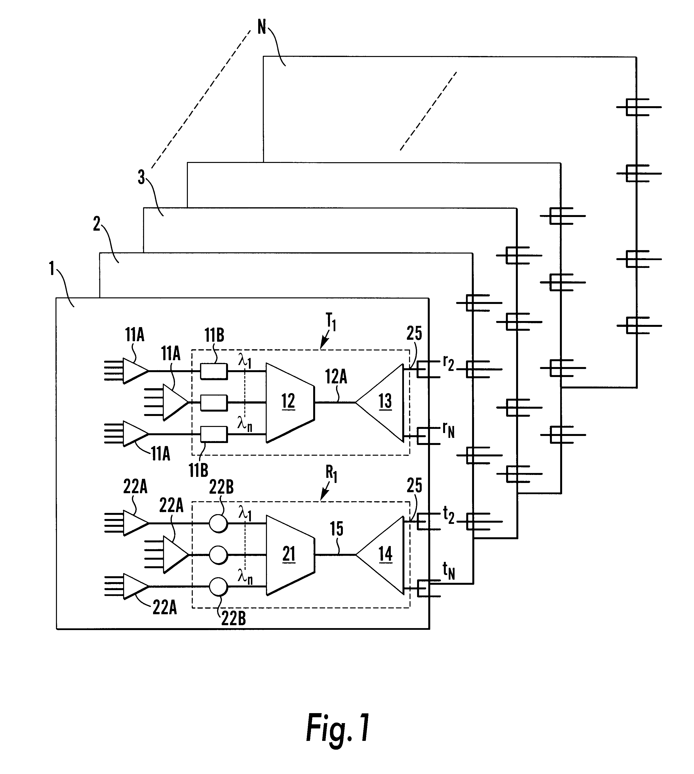
FIG. 1 shows optical circuits for use in connecting N electrical circuit boards 1-N so that each electrical circuit board can communicate with each other electrical circuit board. The optical circuits each comprise a transmitter module T.sub.1 and a receiver module R.sub.1. The optical circus provided on the other electrical circuit boards 2-N similarly comprise transmitter modules T.sub.2 -T.sub.N and receiver modules R.sub.2 -R.sub.N. The optical circuits are associated with the respective electrical circuit boards 2-N and may be mounted thereon as shown in FIG. 1.

The optical circuit boards preferably comprises one or more silicon-on-insulator (SOI) chips as will be discussed further below.

The transmitter module T.sub.1 comprises electrical to optical converters which receive data from the first electrical circuit board 1 and convert the data into modulated optical signals. The electrical data is typically provided in parallel form and is converted to a serial data stream by elect...


PUM


Abstract

Apparatus connecting electrical circuit boards (1, 2, 3, . . . N) so each board can communicate with each other. Each board has an optical circuit, which in turn has a transmitter module (T) and a receiver module (R). The transmitter module (T) has electrical to optical converters (11B) for converting electrical signals into optical signals, a wavelength multiplexer (12) for multiplexing the optical signals into a single optical waveguide (12A), and an optical splitter (13) for dividing the multiplexed signal into a plurality of identical signals for transmission to each of the receiver modules (R). The receiver module (R) has an optical selector (14) for selecting signals from the transmission modules (T), a wavelength demultiplexer (21) for demultiplexing the selected signal into signals each of a different wavelength (lambd1 . . . lambdn), and optical to electrical converters (22B) for converting each of the signals of different wavelengths into an electrical signal.

Description

This invention relates to apparatus for use in connecting a plurality of electrical circuit boards so each electrical circuit board can communicate with each other electrical circuit board.Current switch fabrics employed in high bandwidth switches e.g. Asynchronous Transfer Mode switches and Synchronous Optical Networking Standards / Synchronous Digital Hierarchy SONET / SDH currently interconnect circuit boards via an electrical back plane. Where signals are required to be switched between circuit boards, an electrical switch fabric is also used, with all data paths routed via the back plane to the witch fabric. In order to increase the bandwidth of such systems, the capacity of the back planes and switch fabrics must be increased, with wider data paths and higher clock frequencies. Pin Counts, high clock frequencies and electromagnetic interference (EMI) make this problematic.Optical back planes and switch fabrics offer the possibility of an architecture which is essentially independe...

Claims


Application Information

Patent Timeline
Patent Type & Authority Patents(United States)
IPC IPC(8): G02B6/34G02B6/43H04B10/00H05K1/02H05K1/14H04B10/80
CPCG02B6/29355G02B6/4215G02B6/43H04B10/803H05K1/0274H05K1/14
Inventor DAY, IAN EDWARD
Owner LUMENTUM TECH UK LTD
Why Eureka
Try Eureka