

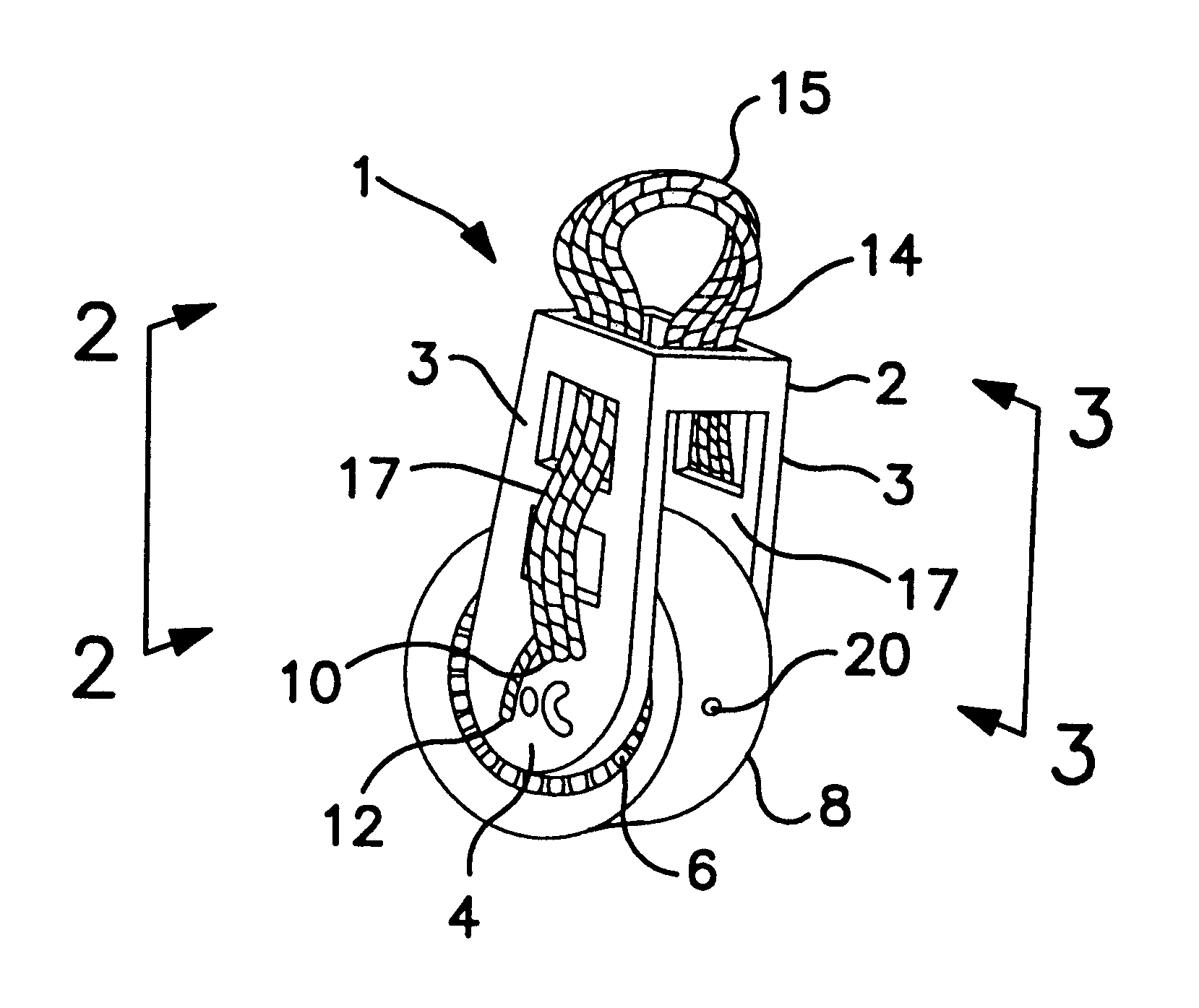
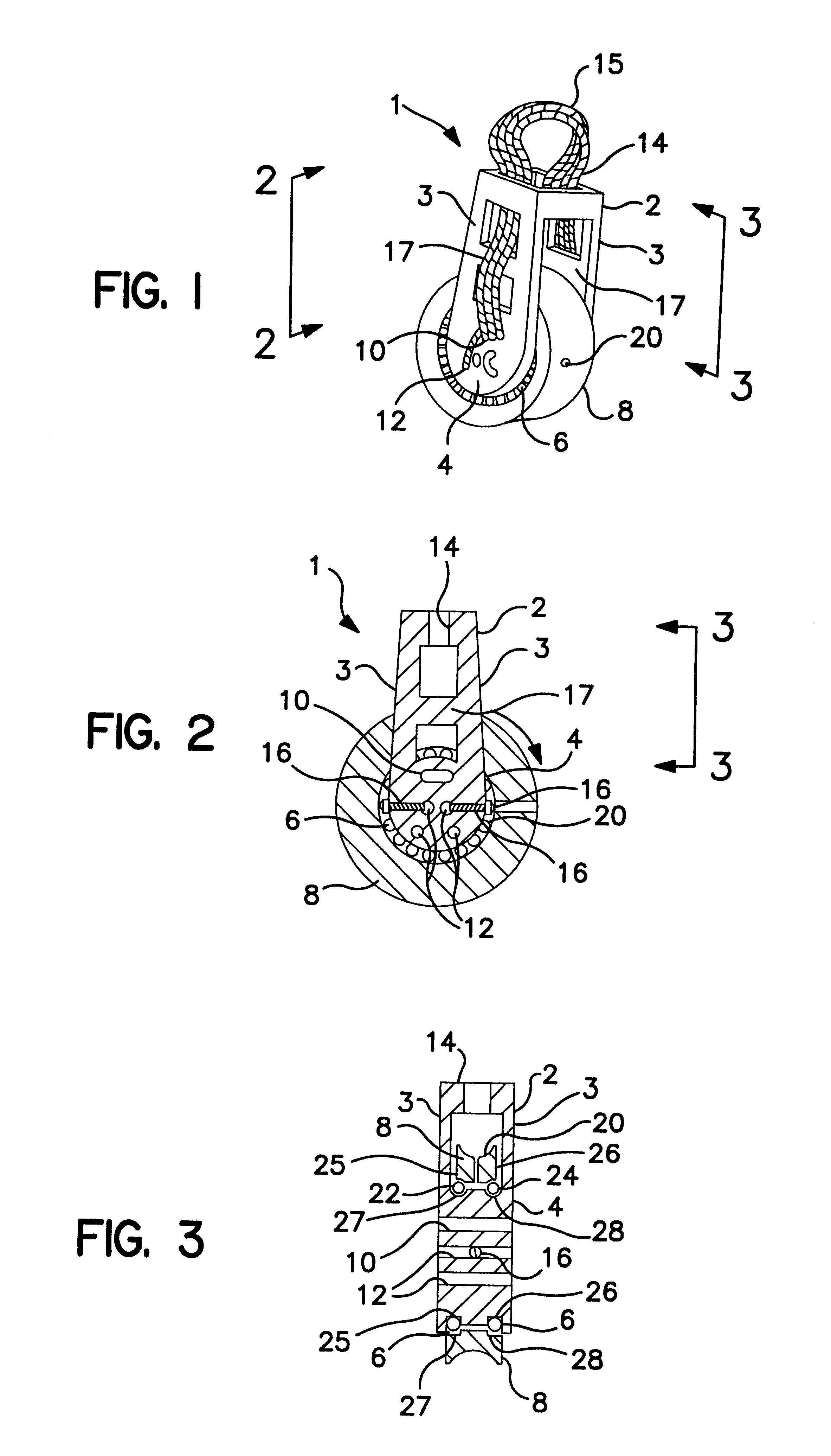
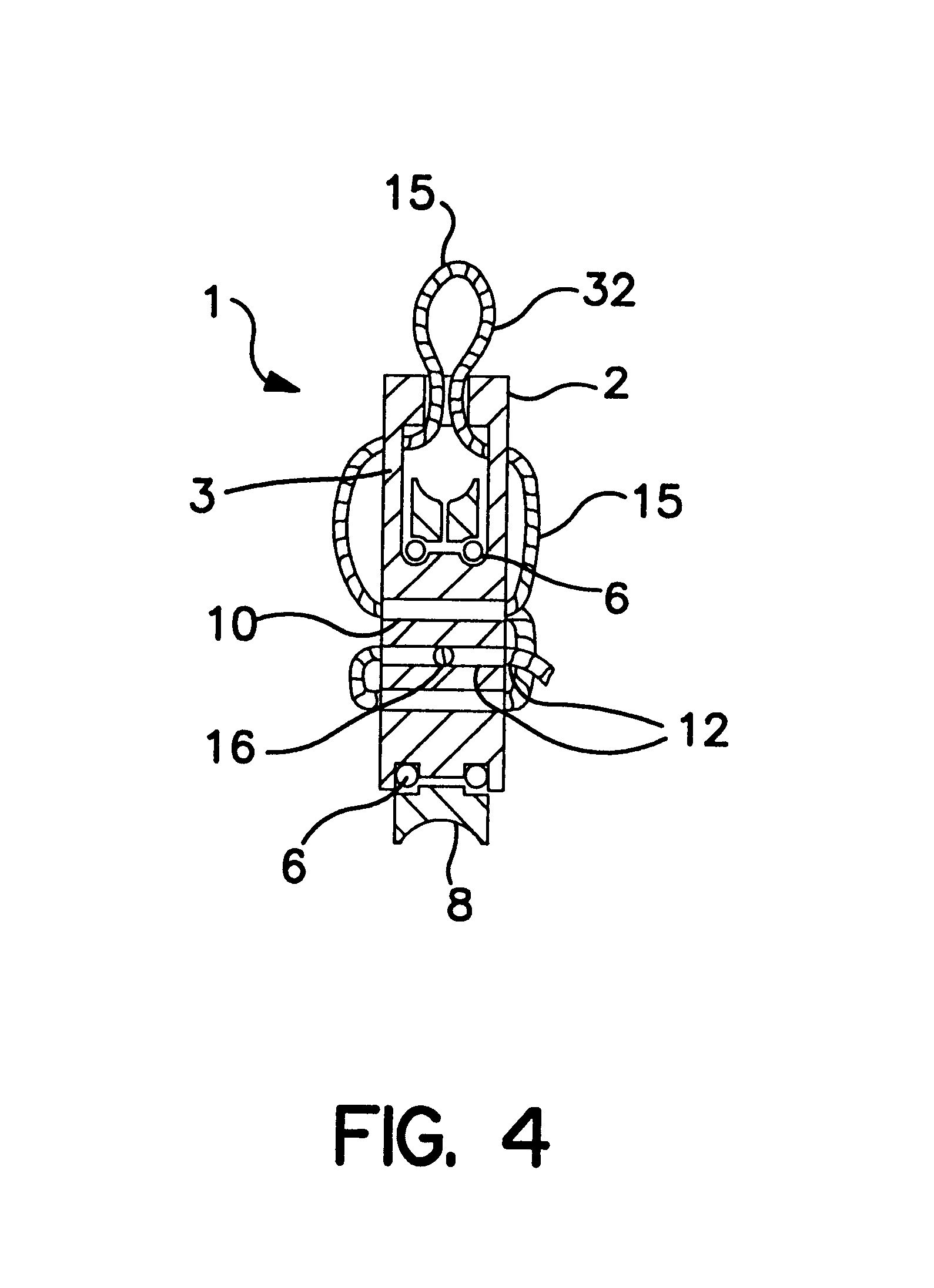
Bearing block tether using fine lines
a technology of bearing block and fine line, which is applied in the direction of marine propulsion, hoisting equipment, vessel construction, etc., can solve the problems of affecting the use of the bearing block in alternate applications, the rigidity of the metal anchor shackle, and the inability to adapt to the application of the bearing block, etc., to achieve the effect of low weight and easy and removable attachment to the boat deck or the lik
- Summary
- Abstract
- Description
- Claims
- Application Information
AI Technical Summary
Benefits of technology
Problems solved by technology
Method used
Image

Examples
second example
FIG. 5: Second Example
FIGS. 5A, 5B, and 5C show a second embodiment of the block of the invention, with locking means comprised within the head of the block. FIG. 5A is a side elevational view, partly in cross section, of block 100, which generally comprises side cheek 102, central hub 104, head 106, and sheave 108 rotatably mounted about central hub 104. A substantially vertical slot 110 (shown in broken line) extends through head 106, with cross pin 112 extending substantially horizontally through slot 110. Slot 110 has first side 114, and second side 116. A substantially horizontal passage intersects slot 110, with a first length 118 connecting to slot first side 114, and a second length 120 connecting to slot second side 116 (both lengths shown in broken line).
A length of high strength cord 122 has a first end portion 124 and a second end portion 126 extended through slot 110. Cord first end portion 124 passes along slot first side 114, by a first side of cross pin 112, then cro...
third example
FIG. 6: Third Example
FIGS. 6A, 6B, and 6C illustrate an additional embodiment of the block of the invention similar to that shown in FIGS. 5A, 5B, and 5C. FIG. 6A illustrates a side elevational view, partly in cross section, of the top portion of block 500 of the invention. Block 500 generally comprises head 502, side cheeks 503, as well as a sheave rotatably mounted about a central hub (sheave and hub not illustrated). Head 502 has a substantially vertical slot 504 with a first side 506 and a second side 508. A cross pin 510 extends horizontally through slot 504. A first locking path 512 intersects with slot first side 506 below cross pin 510, with a second locking path 514 intersecting slot second side 508 also below cross pin 510. A cord 516 has a first end portion 518 passed along slot first side 506, wrapped around the bottom of cross pin 510, and extended along second locking path 514. Cord 516 has second end 520 which passes along slot second side 508, wraps around under cros...
fourth example
FIG. 7: Fourth Example
FIGS. 7A, 7B, and 7C show another embodiment of the block of the invention, with the cord locking means again contained within the block head. Block 150 has head 151, cheeks 152 connecting a central hub 154, with a sheave 156 rotatably mounted about the central hub. Bearing means (not illustrated) facilitate rotation of sheave 156 about hub 154. Head 151 has two sidewalls 158, with a slot formed therebetween. Sidewalls 158 each have inside surfaces 160 a plurality of locking ridges. Two adjustable threaded locking screws 162 are for urging sidewalls 158 towards one another.
A central locking member 164 is contained within the slot between sidewalls 158. Central locking member 164 has two outside walls 166 that oppose sidewall inside surfaces 160. Locking member outside walls 166 have a plurality of locking ridges on them. A length of cord 168 is removably locked in place within head 151 by having its ends wrapped about central locking member 164, with sidewalls ...
PUM
 Abstract
Description
Claims
Application Information