Sequential logic circuit with active and sleep modes

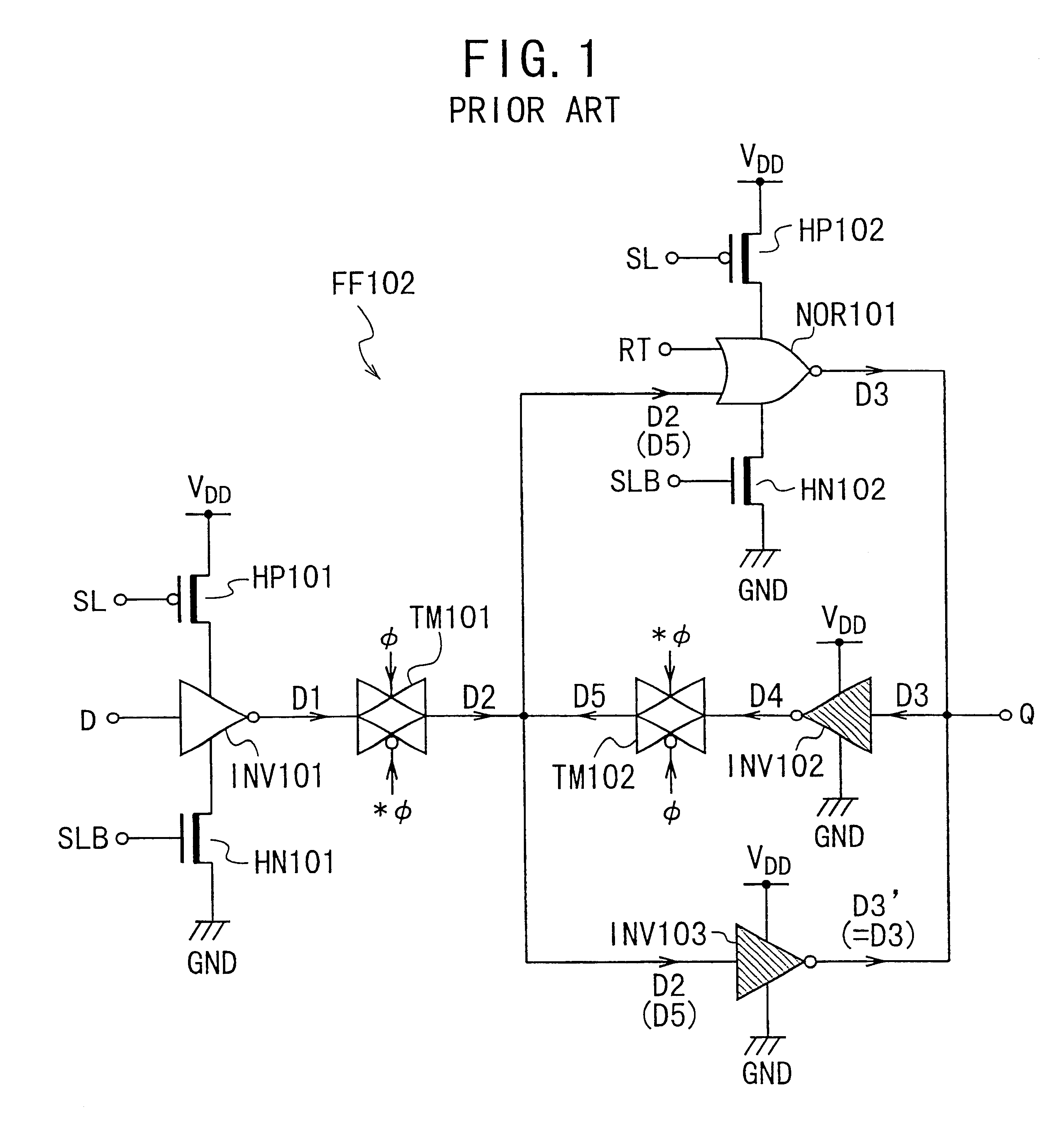
a logic circuit and sleep mode technology, applied in the field of sequential logic circuits, can solve the problems of low decrease the power consumption in sleep mode, and reduce the power consumption of inverters inv102 and inv103

Inactive Publication Date: 2001-10-30
NEC ELECTRONICS CORP
View PDF13 Cites 48 Cited by
  • Summary
  • Abstract
  • Description
  • Claims
  • Application Information

AI Technical Summary

Problems solved by technology

Since the control transistors HP101 and HN101 have the high threshold voltages, they have small subthreshold leakage currents, which decreases the power consumption in the sleep mode.
Since the control transistors HP102 and HN102 have the high threshold voltages, they have small subthreshold leakage currents, which decrease the power consumption.
Since the inverters INV102 and INV103 are formed by the high-threshold MOSFETs, current leakage is small in the sleep mode, resulting in low power consumption of the inverters INV102 and INV103.
With the prior-art sequential logic circuit or latch circuit FF102 shown in FIG. 1, however, there is a problem the value or information of the stored signal D is broken immediately after the transition from the sleep mode to the active mode.
This is due to the different propagation delays of the signals.
Since the control transistors HP1 and HN1 have the high threshold voltages, they have small subthreshold leakage currents, which decreases the power consumption in the sleep mode.
Since the control transistors HP2 and HN2 have the high threshold voltages, they have small subthreshold leakage currents, which decreases the power consumption.
Since the inverters INV2 and INV3 are formed by the high-threshold MOSFETs, current leakage is small in the sleep mode, resulting in low power consumption of the inverters INV2 and INV3.

Method used


Image

  • Sequential logic circuit with active and sleep modes
  • Sequential logic circuit with active and sleep modes
  • Sequential logic circuit with active and sleep modes

Examples


third embodiment

FIG. 8 shows the circuit configuration of a sequential logic circuit SLC3 having sleep and active modes according to a third embodiment of the present invention. The circuit SLC3 has the same configuration as that of the circuit SLC2 according to the second embodiment of FIG. 7, except for the configuration of the first and second switches SW1 and SW2. Thus, only the explanation about the switches SW1 and SW2 is given below.

The first switch SW1 is comprised of a transmission gate TM23 and a control transistor HD21. The transmission gate TM23 is formed by high-threshold MOSFETs. The transmission gate TM23 serves to pass or block the reset signal RT in response to the data keep signal KP and the inverted data keep signal KPB. The transmission gate TM23 blocks the reset signal RT in the data keep mode (i.e., KP=1 and KPB=0), and passes the reset signal RT in the normal mode (i.e., KP=0 and KPB=1).

In the data keep mode, since the pull-down control transistor HD21 is on, the output signa...

fourth embodiment

FIG. 9 shows the circuit configuration of a sequential logic circuit SLC4 having sleep and active modes according to a fourth embodiment of the present invention. The circuit SLC4 has the same configuration as that of the circuit SLC3 according to the third embodiment of FIG. 8, except that the configuration of the first and second switches SW1 and SW2 are illustrated in detail. Thus, only the explanation about the switches SW1 and SW2 is given below.

The transmission gate TM23 is comprised of a high-threshold p-channel MOSFET HP31 and a high-threshold n-channel MOSFET HN31. The source and drain of the n-channel MOSFET HN31 are connected to drain and source of the p-channel MOSFET HP31, respectively, forming a pair of bidirectional terminals. One of the bidirectional terminals, which forms an input terminal of the switch SW1, is applied with the reset signal RT. The other of the bidirectional terminals, which forms an output terminal of the switch SW1, is connected to the reset termi...

fifth embodiment

FIG. 10 shows the circuit configuration of a sequential logic circuit SLC5 having sleep and active modes according to a fifth embodiment of the present invention. The circuit SLC5 has the same configuration as that of the circuit SLC3 according to the third embodiment of FIG. 8, except that the configuration of the first and second switches SW1 and SW2 are illustrated in detail. The circuit SLC5 is a variation of the circuit SLC3. Thus, only the explanation about the switches SW1 and SW2 is given below.

The transmission gate TM23 is comprised of a high-threshold p-channel MOSFET HP41. The source and drain of the p-channel MOSFET HP41 form a pair of bidirectional terminals. One of the bidirectional terminals, which forms an input terminal of the switch SW1, is applied with the reset signal RT. The other of the bidirectional terminals, which forms an output terminal of the switch SW1, is connected to the reset terminal R of the latch circuit FF1. The gate of the p-channel MOSFET HP41 i...


PUM


Abstract

A sequential logic circuit having active and sleep modes prevents stored information from being lost immediately after the transition from a sleep mode to an active mode. This sequential logic circuit includes a latch circuit having an input terminal to which an input signal is applied, an output terminal from which and output signal is derived, and a set and/or reset terminal to which a set and/or reset signal is applied. The latch circuit has an active mode where a latch function is operable and a sleep mode where the latch function is inoperable, one of which is alternatively selected. The output signal is set or reset to have a specific logic state by the set or reset signal having a specific logic level applied to the set or reset terminal in the active mode. The sequential logic circuit further includes circuitry for preventing the set or reset signal from being applied to the set or reset terminal in the sleep mode, thereby avoiding loss of information or data latched in the latch circuit prior to transition to the sleep mode from the active mode. Thus, the information-latch operation in both of the modes is ensured.

Description

1. Field of the InventionThe present invention relates to a sequential logic circuit and more particularly, to a sequential logic circuit equipped with a latch circuit having active and sleep modes.2. Description of the Prior ArtIn recent years, semiconductor integrated logic devices have been designed to cope with both high-speed operation in the active mode and low power-dissipation in the sleep mode. The "active mode" is the state where the normal operation of the logic devices are performed. The "sleep mode" is the state where the normal operation of the logic devices are stopped. The "sleep mode" may be termed the "power-down mode" because of its purpose of reducing the power dissipation. It is important for the semiconductor integrated logic devices of this sort to prevent the stored information in the devices from being broken especially in the sleep mode.An example of the prior-art semiconductor integrated logic devices of this sort is disclosed in the Japanese Non-Examined ...

Claims


Application Information

Patent Timeline
Patent Type & Authority Patents(United States)
IPC IPC(8): H03K3/037H03K3/00H03K3/012G06F1/32G06F1/24
CPCH03K3/012H03K3/0375
Inventor OGAWA, TADAHIKO
Owner NEC ELECTRONICS CORP
Why Eureka
Try Eureka