
Dual-chamber pacemaker with optimized PVARP following event that may disrupt AV synchrony

a dual-chamber, pvarp-optimized technology, applied in electrotherapy, heart stimulators, therapy, etc., can solve the problems of av electrical and mechanical synchrony disruption, initiation of pacemaker-mediated tachycardias or pmts, and prolongation of pvarp in response to pvc. unfortunate consequences

Inactive Publication Date: 2001-10-30
MEDTRONIC INC
View PDF20 Cites 60 Cited by
  • Summary
  • Abstract
  • Description
  • Claims
  • Application Information

AI Technical Summary

Benefits of technology

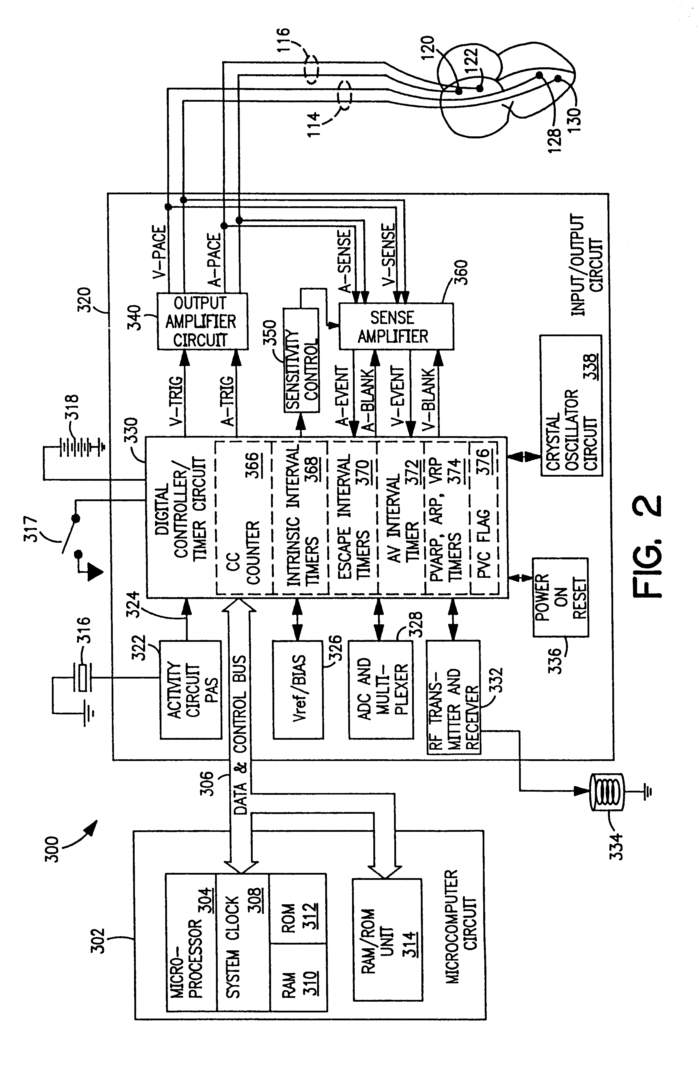
FIG. 2 is a schematic block diagram of major functional blocks of one embodiment of a pacemaker operating system that can be employed in accordance with the present invention to carry out the timing of an appropriate PVARP in response to a PVC or other AV synchrony disrupting event to avoid persistent loss of AV synchrony;

Problems solved by technology

The disruption of AV electrical and mechanical synchrony frequently arises due to the spontaneous depolarization of the ventricles triggered at an ectopic site in one of the ventricles.
One such problem is the initiation of pacemaker mediated tachycardias or PMTs.
Unfortunately, in some circumstances prolongation of the PVARP in response to a PVC has unfortunate consequences.
A similar problem may arise in response to other events which disrupt AV synchrony.
In particular, changes from non-atrial synchronized pacing modes to atrial synchronized pacing modes or from non-atrial synchronized operation to atrial synchronized operation within an atrial synchronized pacing mode have the potential to disrupt AV synchrony.
In the context of pacemakers which employ PVARPs which vary as a function of pacing rate or sensed atrial rate, the relatively long PVARPs which may be in effect at lower rates can in the same fashion result in persistent loss of AV synchrony due to PVCs or other disrupting events even in the absence of extension of the PVARP.

Method used


Image

  • Dual-chamber pacemaker with optimized PVARP following event that may disrupt AV synchrony
  • Dual-chamber pacemaker with optimized PVARP following event that may disrupt AV synchrony
  • Dual-chamber pacemaker with optimized PVARP following event that may disrupt AV synchrony

Examples


Embodiment Construction

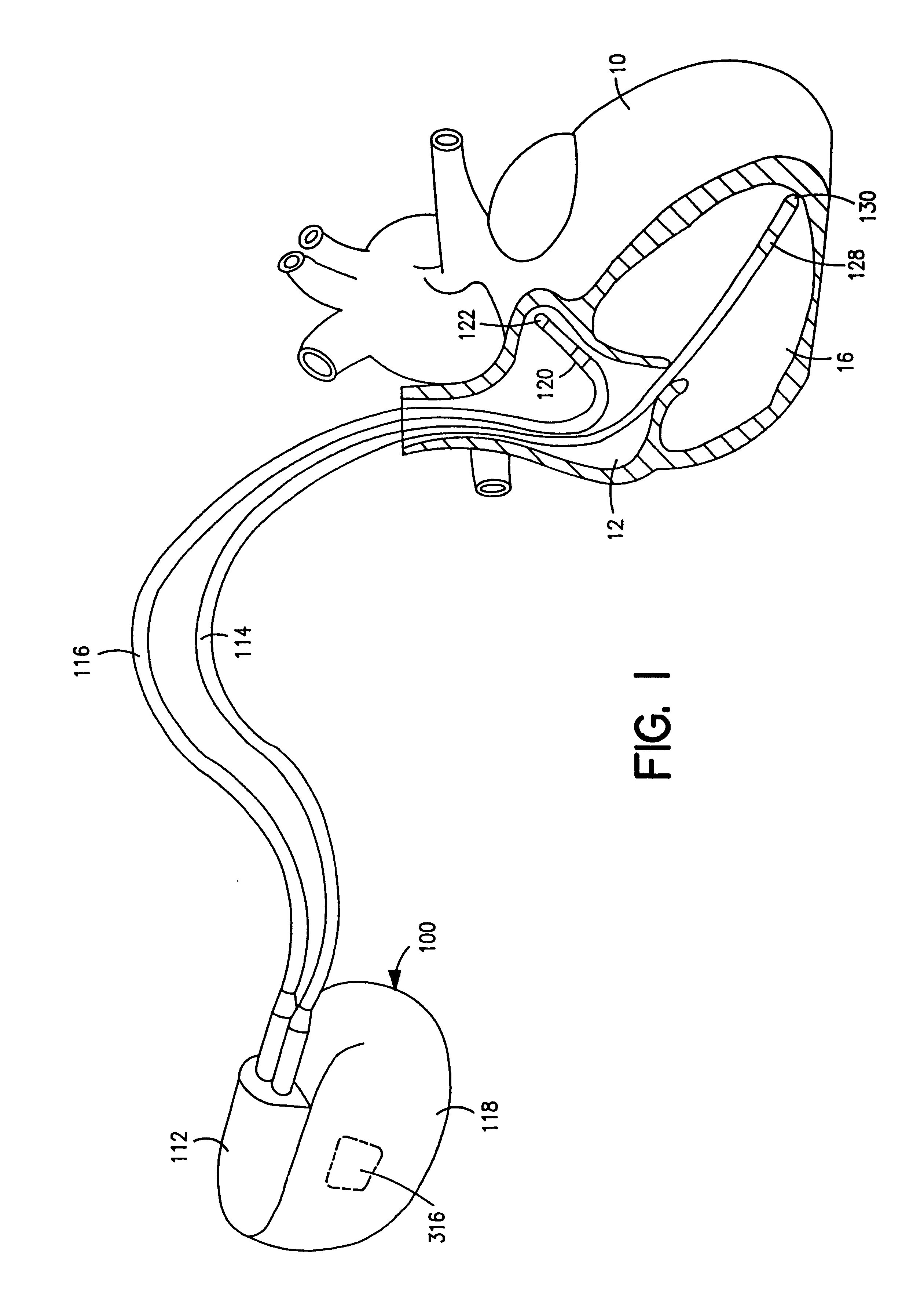
FIG. 1 depicts the external configuration of a typical implantable dual chamber pacemaker, e.g. a VDD, VDDR, DDD or DDDR pacemaker, comprising dual chamber IPG 100 and unipolar or bipolar atrial and ventricular leads 114 and 116 (bipolar leads are depicted), in which the present invention may be implemented. The DDD and DDDR pacemaker IPGs sense and pace in the atrial and ventricular chambers, and pacing is either triggered and inhibited depending upon sensing of intrinsic, non-refractory atrial and ventricular depolarizations during the sequentially timed V-A interval and AV delay, respectively, as is well known in the art. Such DDD and DDDR pacemaker IPGs effectively function in a VDD pacing mode when the sinus atrial heart rate varies within the lower rate and the upper rate limit and such intrinsic atrial depolarizations are consistently sensed. The present invention can be implemented as well into VDD and VDDR pacemakers that are implanted in patients with healthy sinus atrial ...


PUM


Abstract

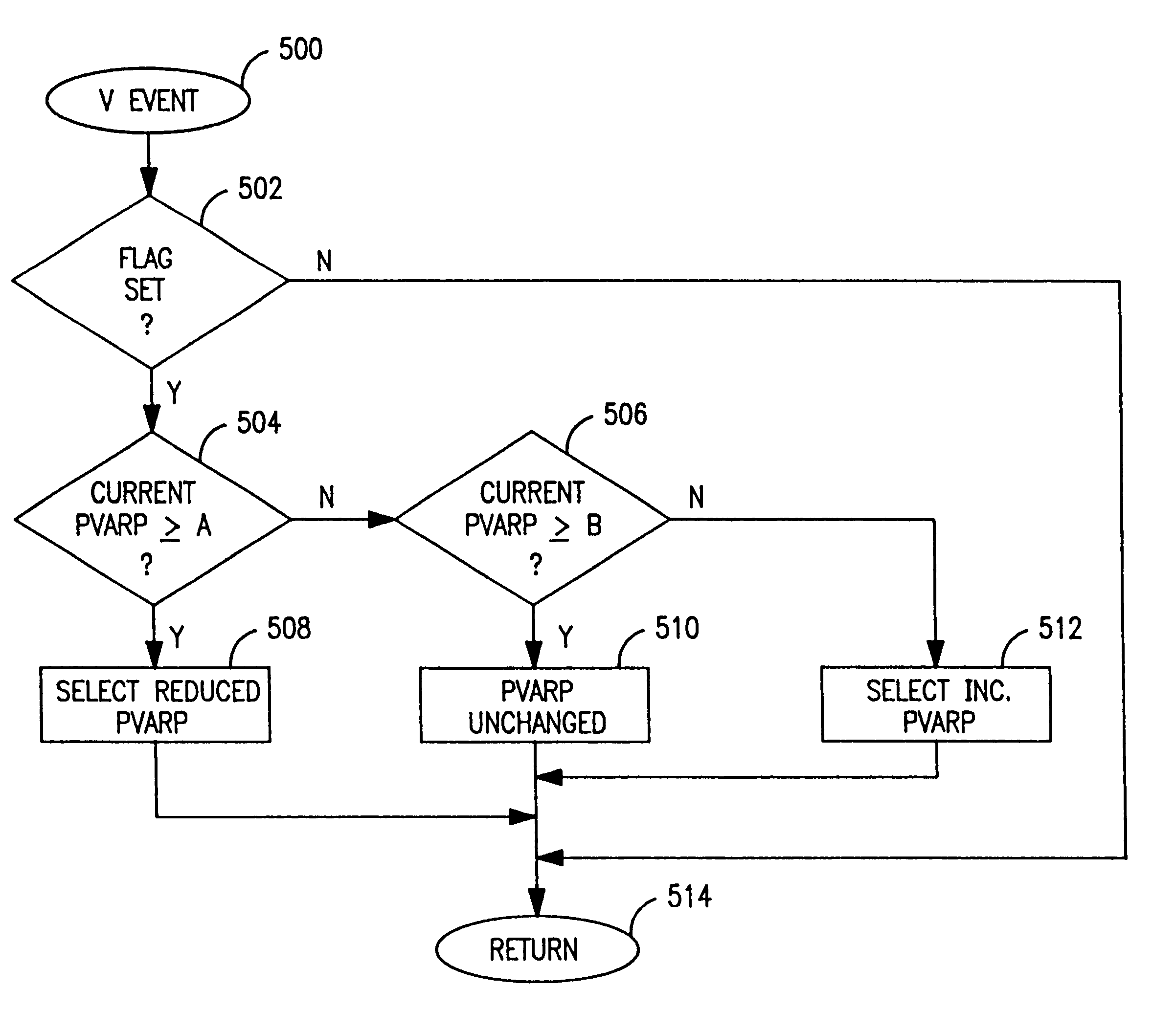
A pacemaker and a method of employing a pacemaker to pace a patient's heart. The method of operation of the pacemaker includes defining a post ventricular atrial refractory period having a first duration responsive to ventricular events, during which period the pacemaker does not initiate timing of an AV delay responsive to detected atrial depolarizations and in response to events which a may disrupt AV synchrony, such as PVC's, mode changes and the like, defining a post ventricular atrial refractory period having a second duration less than the first duration. The shortened post ventricular atrial refractory period remains in effect only temporarily, for example for one cardiac cycle, and may be initiated on a ventricular event which is the disrupting event or immediately follows the disrupting event, or may be initiated following a later ventricular event.

Description

The present invention relates to implantable dual chamber pacemakers, including rate responsive pacemakers, and to an improved response to premature ventricular contractions (PVCs) and other events which may disrupt the timing of pacing functions.Atrial synchronized dual chamber pacing modes, particularly, the multi-programmable, VDD, VDDR, DDD and DDDR pacing modes, have been widely adopted in implantable dual chamber pacemakers for providing atrial and ventricular or AV synchronized pacing on demand. A pacemaker implantable pulse generator (IPG) capable of pacing in atrial synchronized modes typically includes an atrial sense amplifier to detect atrial depolarizations or P-waves and generate an atrial sense event (A-SENSE) signal, a ventricular sense amplifier to detect ventricular depolarizations or R-waves and generate a ventricular sense event (V-SENSE) signal, a ventricular pacing pulse generator and for DDD or DDDR mode pacing an atrial pacing pulse generators as well, provid...

Claims


Application Information

Patent Timeline
IPC IPC(8): A61N1/362
CPCA61N1/3622
Inventor BETZOLD, ROBERT A.WARMAN, EDUARDO N.
Owner MEDTRONIC INC
Learn More