Urinary sphincter control device

a technology of urinary sphincter and control device, which is applied in the field of urinary sphincter control device, can solve the problems of tissue damage and the subsequent need to remove the device from the patient, and affect the force imposed by the device on the urethra of the patien

Inactive Publication Date: 2001-11-20
ICD LABS
View PDF12 Cites 14 Cited by
  • Summary
  • Abstract
  • Description
  • Claims
  • Application Information

AI Technical Summary

Problems solved by technology

However, the cuff can also restrict the flow of blood along the urethra, leading to tissue damage and the subsequent need to remove the device from the patient.
They can also affect the forces that are imposed by the device on a patient's urethra.

Method used


Image

  • Urinary sphincter control device
  • Urinary sphincter control device
  • Urinary sphincter control device

Examples


Embodiment Construction

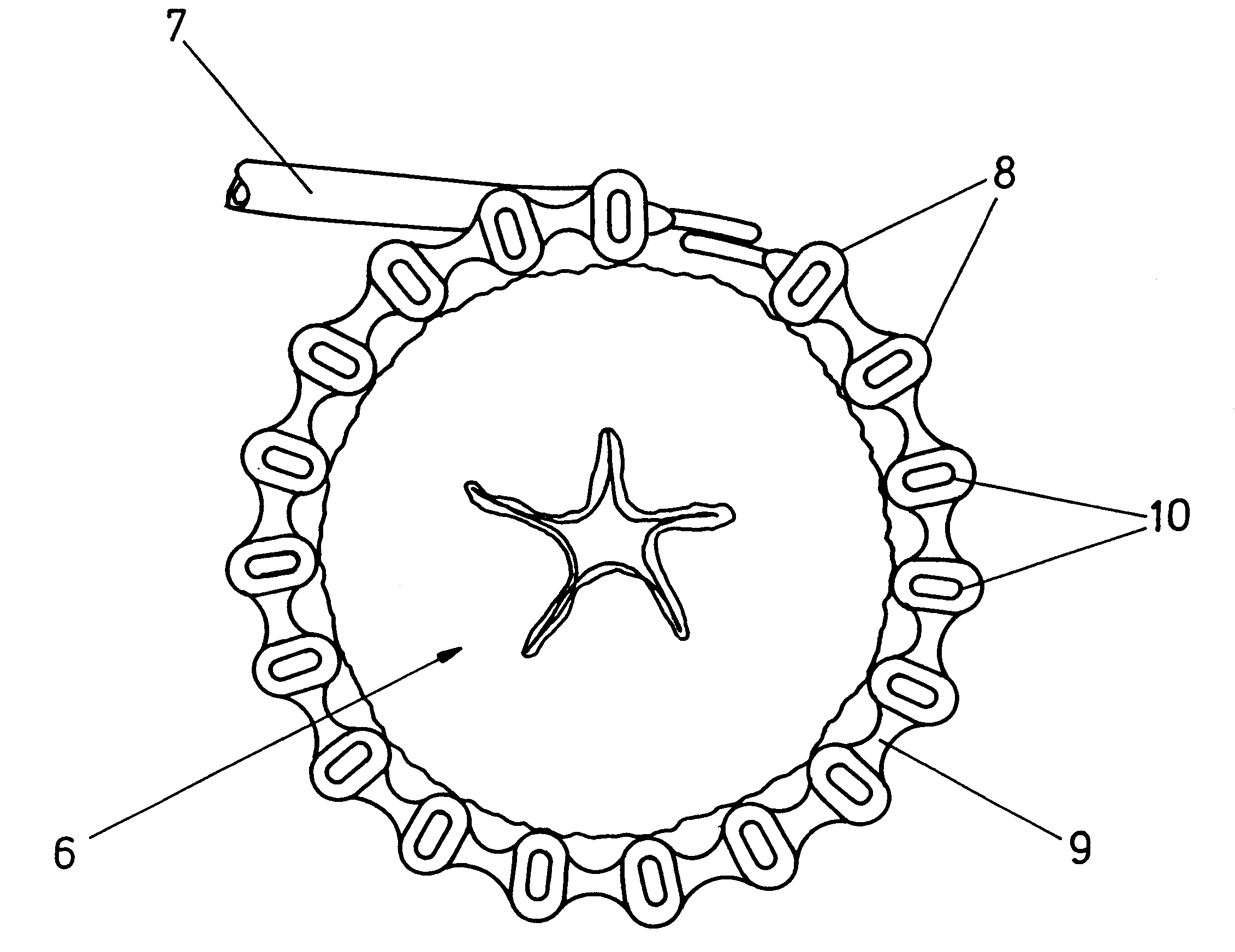
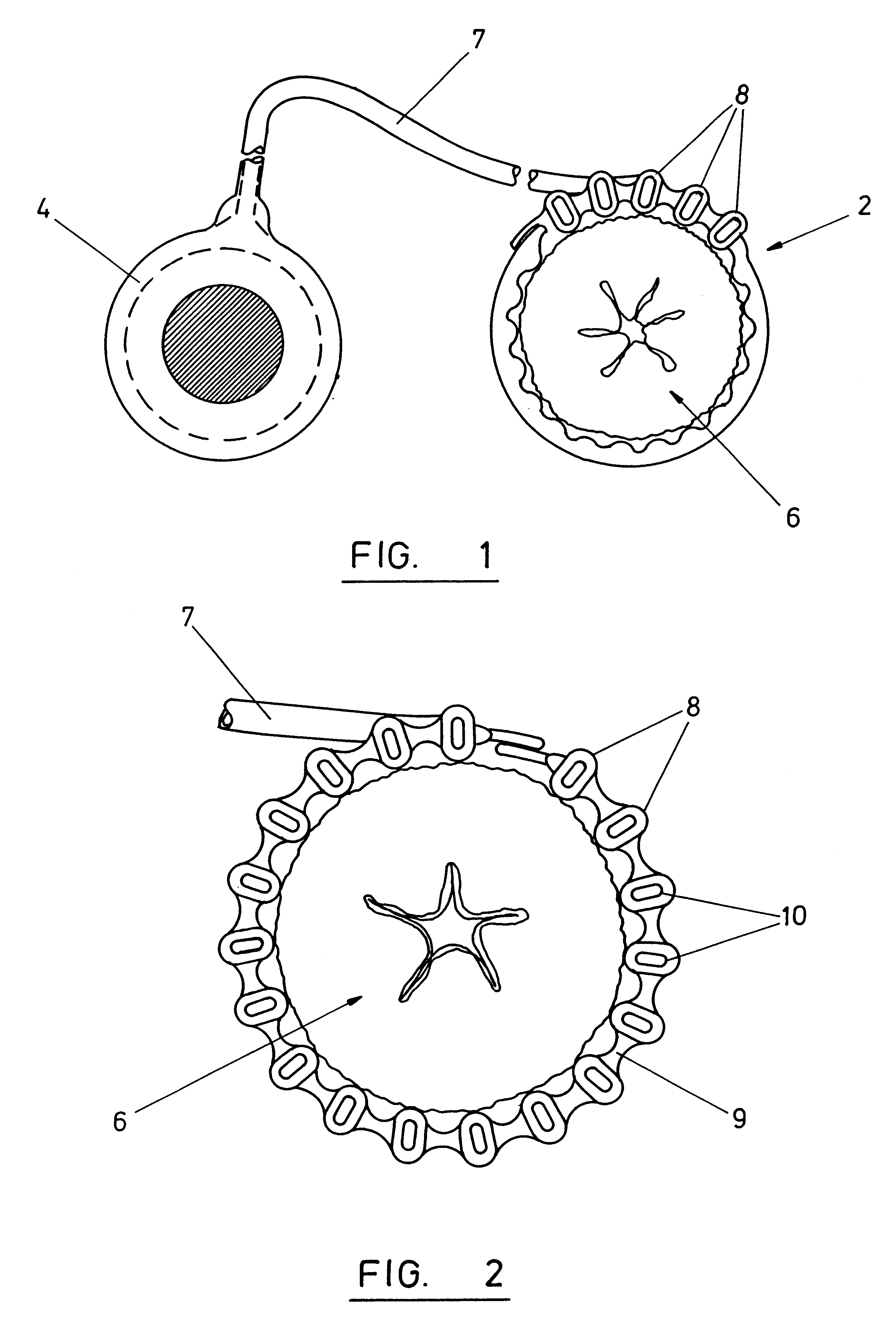
FIG. 1 shows a urinary sphincter control device which comprises a multi-chamber cuff 2 which can be positioned around a urethra 6 and an actuator 4. The cuff comprises a plurality of substantially parallel chambers 8 which extend through the cuff in line with the axis of the cuff. Each of the chambers can be inflated by means of hydraulic fluid whose pressure can be adjusted by means of the actuator 4.

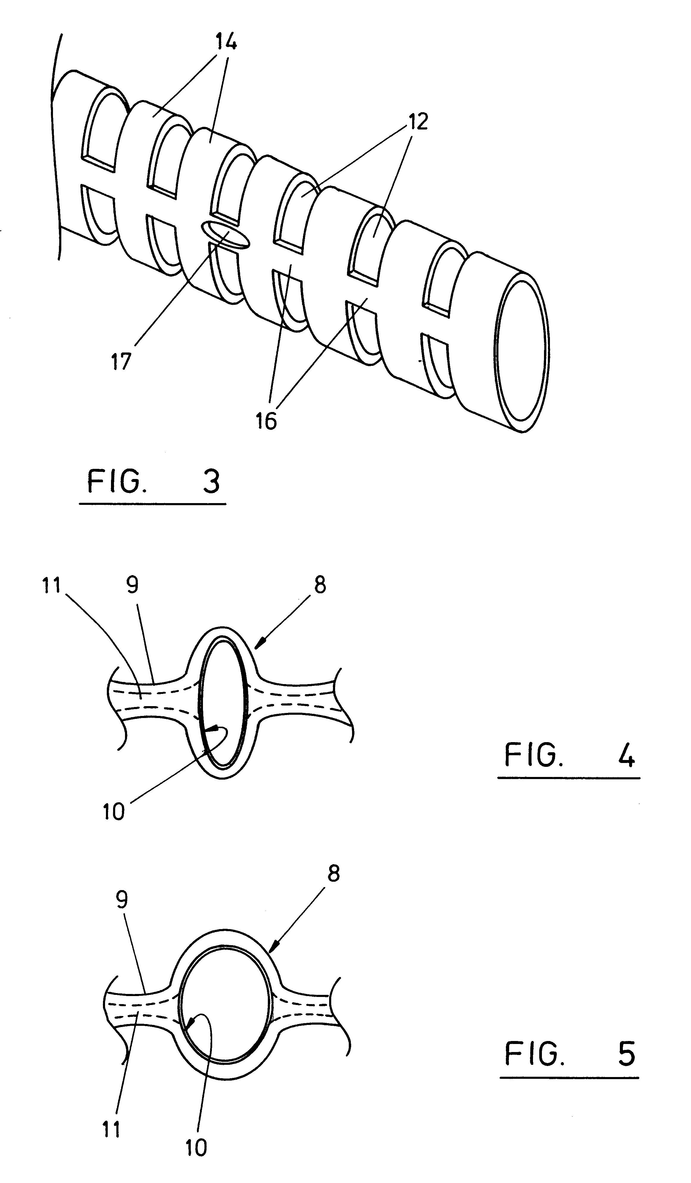
The cuff comprises eighteen chambers. The length of the cuff is about 15 mm. The internal perimeter dimension of each of the chambers is about 4 mm. The chambers are in fluid communication with one another to admit pressurised control fluid that is supplied from the actuator 4 through a supply line 7. The chambers are connected to one another by a web 9. The distance between adjacent chambers is about 1.5 mm. Fluid communication between adjacent chambers is provided by a control fluid passage 11 in the webs.

As shown in FIG. 2, each of the chambers 8 contains a tubular biassing element ...


PUM


Abstract

A urinary sphincter control device for application to a urethra to control flow of fluid through the urethra, comprises a cuff which can be fitted around the urethra. The cuff comprises a plurality of chambers which extend generally parallel to the axis of the cuff, and which can be inflated by supply of pressurised control fluid thereto. Inflation of the chambers causing the configuration of the cuff to change so as to alter the resistance that is provided by the cuff to flow of fluid along the urethra.

Description

BACKGROUND TO THE INVENTIONThis invention relates to a urinary sphincter control device for application to a urethra to control flow of fluid through the urethra.Known devices for controlling incontinence comprise a cuff which can be fitted around a patient's urethra. The cuff comprises at least one chamber which extends around the urethra. A pressurised control fluid can be supplied to the cuff to inflate it, causing the cuff to exert compressive pressure onto the urethra so that flow of fluid along the urethra is prevented. The fluid that is used in such devices might be for example a saline solution. The device will generally include a reservoir for the fluid, and a pump by which pressurised fluid can be supplied to the cuff and withdrawn from the cuff. Known devices include an elastic balloon reservoir by which the pressure of the fluid in the cuff can be controlled within predetermined limits.A cuff which extends around the urethra has been found to close a urethra satisfactori...

Claims


Application Information

Patent Timeline
Patent Type & Authority Patents(United States)
IPC IPC(8): A61F2/00
CPCA61F2/004Y10S128/25
Inventor KRUMME, JOHN F.
Owner ICD LABS
Why Eureka
Try Eureka