Double diaphragm precision throttling valve

a technology of throttling valve and diaphragm, which is applied in the direction of diaphragm valve, engine diaphragm, operating means/release devices of valves, etc., can solve the problems of small cracks and crevasses, o-rings other materials that may not be compatible with process fluid, etc., to avoid backlash or create excessive noise or wear during operation, reduce backlash, and minimize backlash

Inactive Publication Date: 2001-11-27
ENTEGRIS INC
View PDF2 Cites 48 Cited by
  • Summary
  • Abstract
  • Description
  • Claims
  • Application Information

AI Technical Summary

Benefits of technology

The rotor is fixed in position by thrust bearings captured between the rotor and the drive housing. The rotor is free to turn under all vertical loads, and will position the drive shaft, and diaphragms down onto the flow island to close the flow path, or re positioning the diaphragms in the upward direction, to progressively open the path to fluid flow. The lower bearing assembly is the smaller of the two. Its only function is to produce a small vertical pre load on the rotor. Since all positive fluid pressures will be in the same direction the pre load is only set so that at zero, or slightly negative fluid pressures, the rotor will still have some vertical loading. The vertical load on the rotor will increase directly with fluid pressure. At 60 psi this load will be 105 lbs. The large bearing assembly is sized to take this loading with a conservative margin. Thus the rotor is free to turn under all anticipated loads. Furthermore, the loading will be in the same vertical direction under all anticipated circumstances minimizing backlash.
The top of the rotor has a slot cut in it to receive a plastic insert of moderate hardness. This insert also contains a slot that matches a tab machined on the drive shaft of the motor. There is a slight interference in the fit of the motor tab and the plastic insert. The reason for this is that the motor in modulating the flow under the command of a remote electronic system will be undergoing constant reversals. This interference assures that the slot and tab will not have any backlash or create excessive noise or wear during operation.

Problems solved by technology

This introduces both small cracks and crevasses, as well as another material(the o-ring) that may not be compatible with the process fluid.
Here a metallic actuation shaft is buried in the flexible diaphragm such that it is susceptible to corrosion from ionic migration from some process fluids.
Secondly, this valve contains a large number of parts of metallic content as well as a comparative large volume of fluid should the primary diaphragm fail.
Generally valve designs described in the art attack one or two of the problems described, but none approach the whole problem of safely handling highly toxic or corrosive fluids while providing a smooth continues laminar flow in a free draining, low captive volume device.
Many fluids are both hazardous and suffer detrimental effects to sheer effects when flowing around such obstructions.
Any configuration that results in the flow response being linear over a portion of the range and transitioning to square law at some point will have a detrimental effect on the ability of the controller to smoothly regulate the flow.
Generally drive mechanisms described in the references were judged as incapable of continuous repositioning, or would exhibit excessive backlash detrimental to smooth fluid control.

Method used


Image

  • Double diaphragm precision throttling valve
  • Double diaphragm precision throttling valve
  • Double diaphragm precision throttling valve

Examples


Embodiment Construction

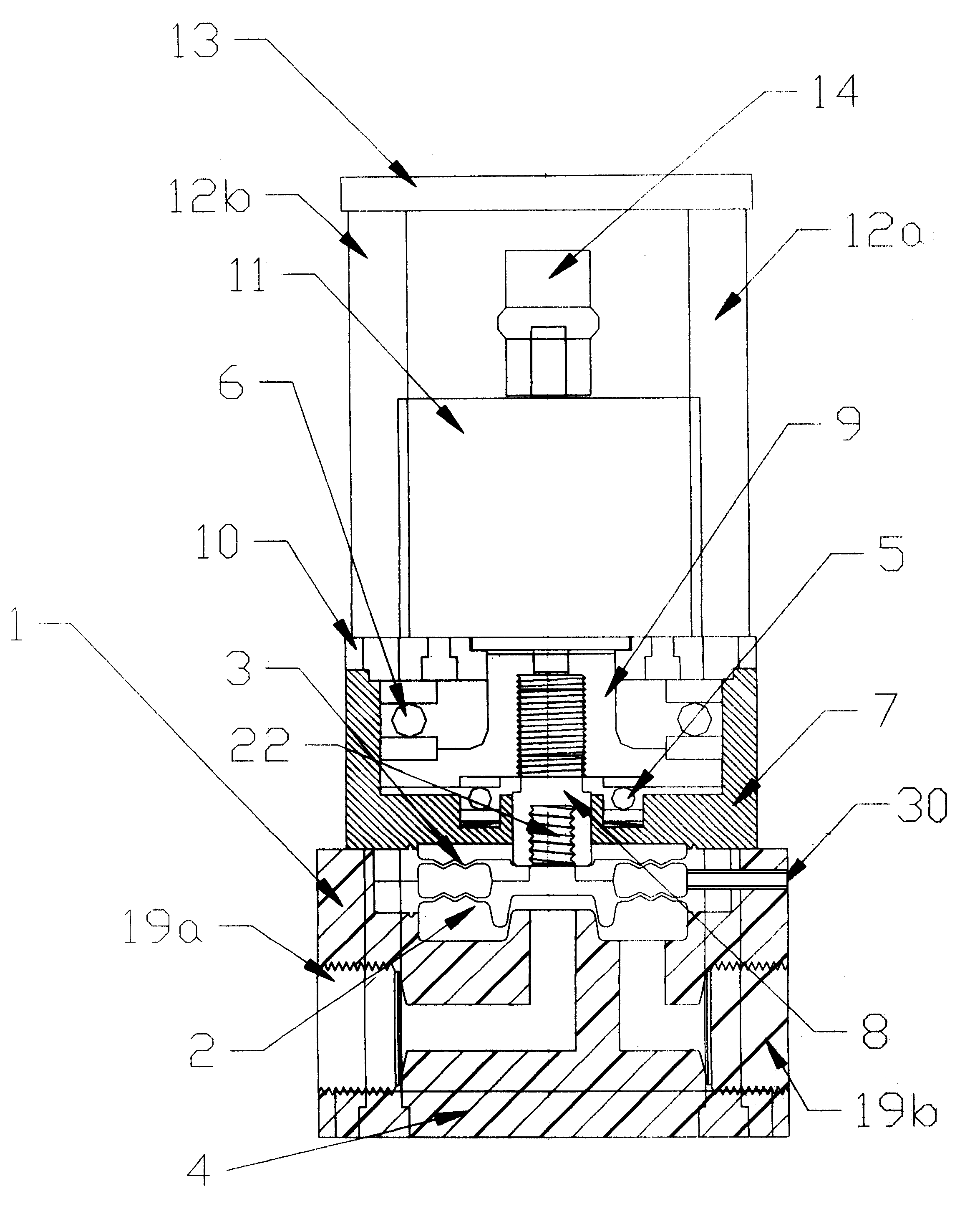
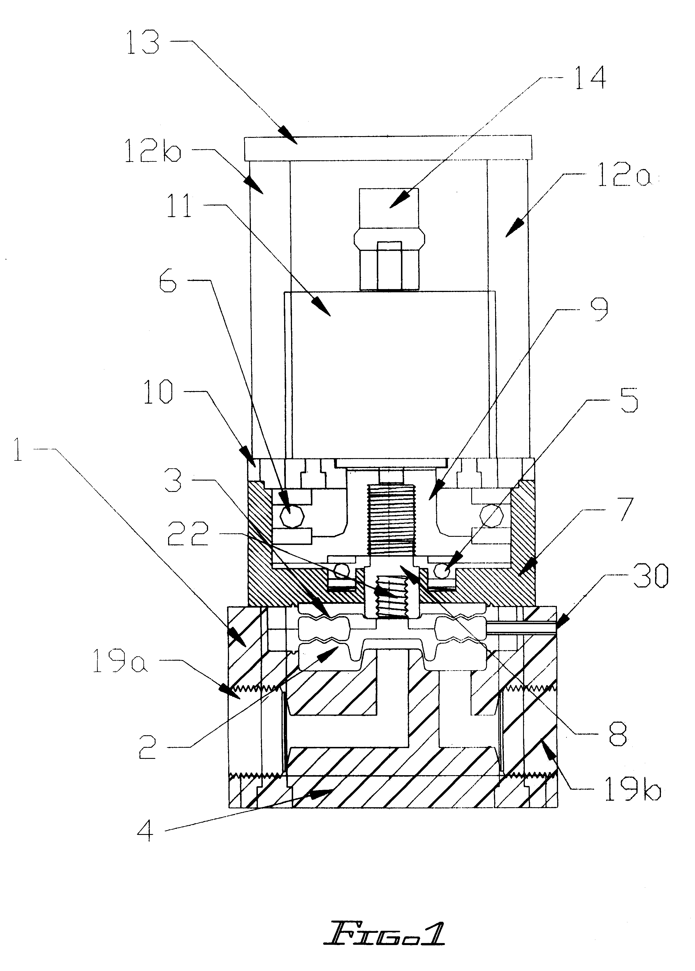
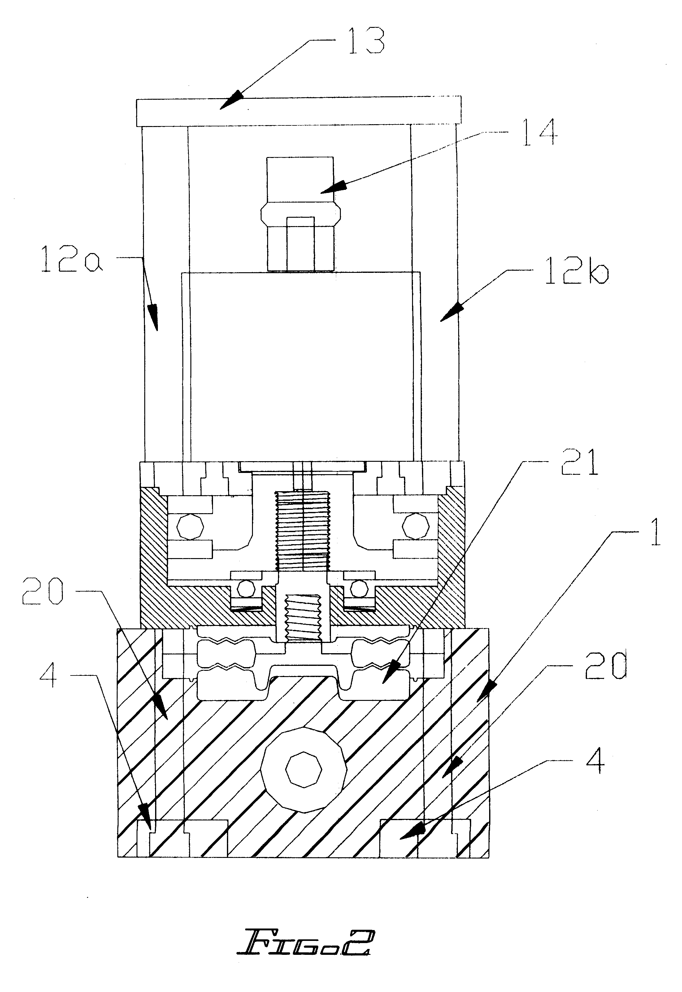
The inlet 19a provides a threaded coupling to the users process fittings and communicates the fluid though to the integral diaphragm and throttling surface 2. From this point the fluid flow is controlled into the inner valve cavity where it is then free to flow to the exit port 19b. The valve body 1 is made from a solid block of Teflon(PTFE, in this case). The primary diaphragm 2 and back up diaphragm 3 are pinched and held in place by the drive housing 7. The drive housing is firmly attached to the valve body as described below. Sealing is accomplished without the need for o-rings by slightly over sizing the shoulders of the two diaphragms 24. The primary diaphragm has the throttling surface machined onto the lower side and a threaded stem 22 machined onto the upper side. This throttling surface is the female form of the discharge island. The threaded stem is used to connect to the drive shaft 8 as well as pinch the backup diaphragm 3 onto the primary diaphragm 2. The drive shaft 8...


PUM


Abstract

A throttling valve assembly actuated by a stepper motor having a double diaphragm seal and integral throttling surface. The throttling surface interfaces to a mating orifice and port arrangement to provide a smooth control regime for various process fluids. Because of the unique design of the flow paths the fluids will remain in a laminar flow state throughout the throttling range, thus providing smooth and continuous response to the control input. The valve opening to the fluid controlled by a stepper motor through a direct drive mechanism. The embodiment shown here employees all PTFE construction for the wetting parts, but any material could be used that would be compatible with the process fluid. Additional features are minimal capture of the process fluid, free draining, and no metallic parts in close communication with the process fluid.

Description

The present invention relates to fluid control devices and in particular to those applications where materials of construction must be compatible with the process fluids and where it is a requirement that minimal volumes of fluids are captured within the valve. Often times the only suitable material meeting these requirements will be PTFE or other Teflon types. Furthermore, these applications often require that no cracks or crevices are present to permanently capture fluids or particulate carried by the fluid. Another requirement where slurries are being controlled is that the fluid should not be subjected to high rates of shear. Lastly, these fluids are often highly toxic and a double containment is necessary for any thin walled barrier in contact with the fluid.BACKGROUND OF INVENTIONMany forms of throttling valve are found within the field. Viraraghavan describes a valve in patent '530(cited in the references) that that is typical of valves that may, at first, may be deemed to be...

Claims


Application Information

Patent Timeline
Patent Type & Authority Patents(United States)
IPC IPC(8): F16K7/12F16K7/14
CPCF16K7/14F16K31/04Y10T137/5762
Inventor PRATT, WAYNE L.KOLARIK, WILLIAM MICHAEL
Owner ENTEGRIS INC
Why Eureka
Try Eureka