Rotary motor and production method thereof, and laminated core and production method thereof

a technology of rotary motors and production methods, which is applied in the direction of stator/rotor bodies, magnetic circuit rotating parts, magnetic circuit shapes/forms/construction, etc., can solve the problems of inability to increase the coiling speed more than 1 and the stator teeth facing inward of the stator are difficult to wind

Inactive Publication Date: 2001-11-27
MITSUBISHI ELECTRIC CORP
View PDF134 Cites 45 Cited by
  • Summary
  • Abstract
  • Description
  • Claims
  • Application Information

AI Technical Summary

Problems solved by technology

The stator shown in FIG. 139 has an integrated ring shaped stator core and therefore, it is difficult to wind the magnetic pole teeth facing inward of the stator with stator coil.
However, because the inside of the stator core is small, the structure of the winding apparatus is complicated.
Additionally, the coiling speed cannot be increased more than 1,000 rpm thereby suppressing the productivity of coiling low.
It is impossible to increase the number of slots because the number of slots is restricted by the difficulty of coiling, thereby obstructing the increase of torque and resulting in torque ripple.
Although winding wire of the coil neatly contributes to compacting and enhancement of the characteristic and reliability of the coil, it is impossible to wind wire neatly because the space between the stator core and the winding apparatus is very small.
Because the shape of the magnetic pole teeth of the stator core is complicated, it is impossible to wind wire effectively.
For the reason, productivity is so low that cost increases and further a special winding apparatus is required.
Although the stator shown in FIGS. 142A, 142B was proposed to solve the aforementioned problem, it is impossible to achieve effective winding of wire if the number of slots is increased to improve the characteristic of the motor.
Further, magnetic resistance increases at portions in which divided stator portions are combined by engagement and air gap is unequalized, so that the cha

Method used


Image

  • Rotary motor and production method thereof, and laminated core and production method thereof
  • Rotary motor and production method thereof, and laminated core and production method thereof
  • Rotary motor and production method thereof, and laminated core and production method thereof

Examples


embodiment 1

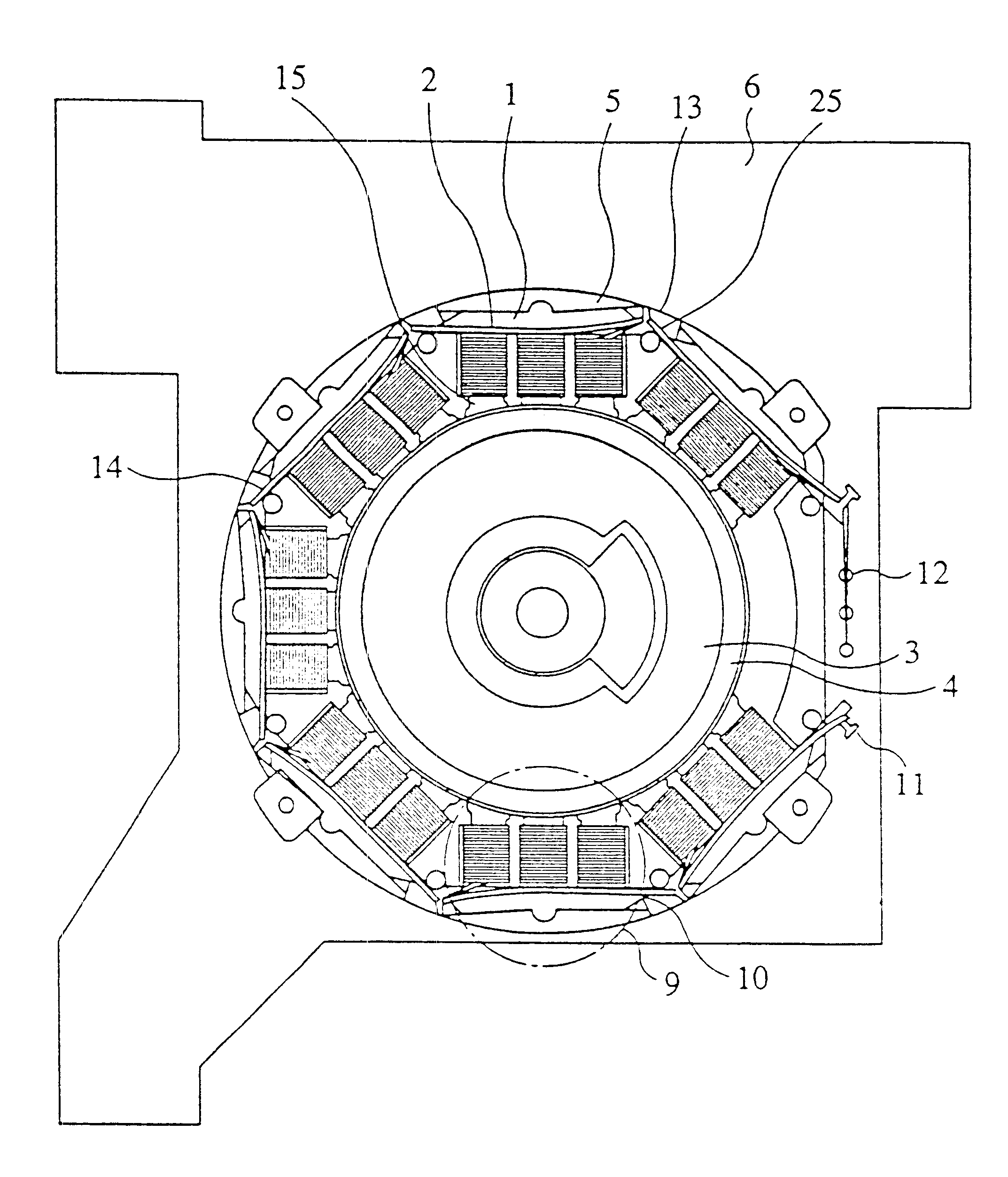
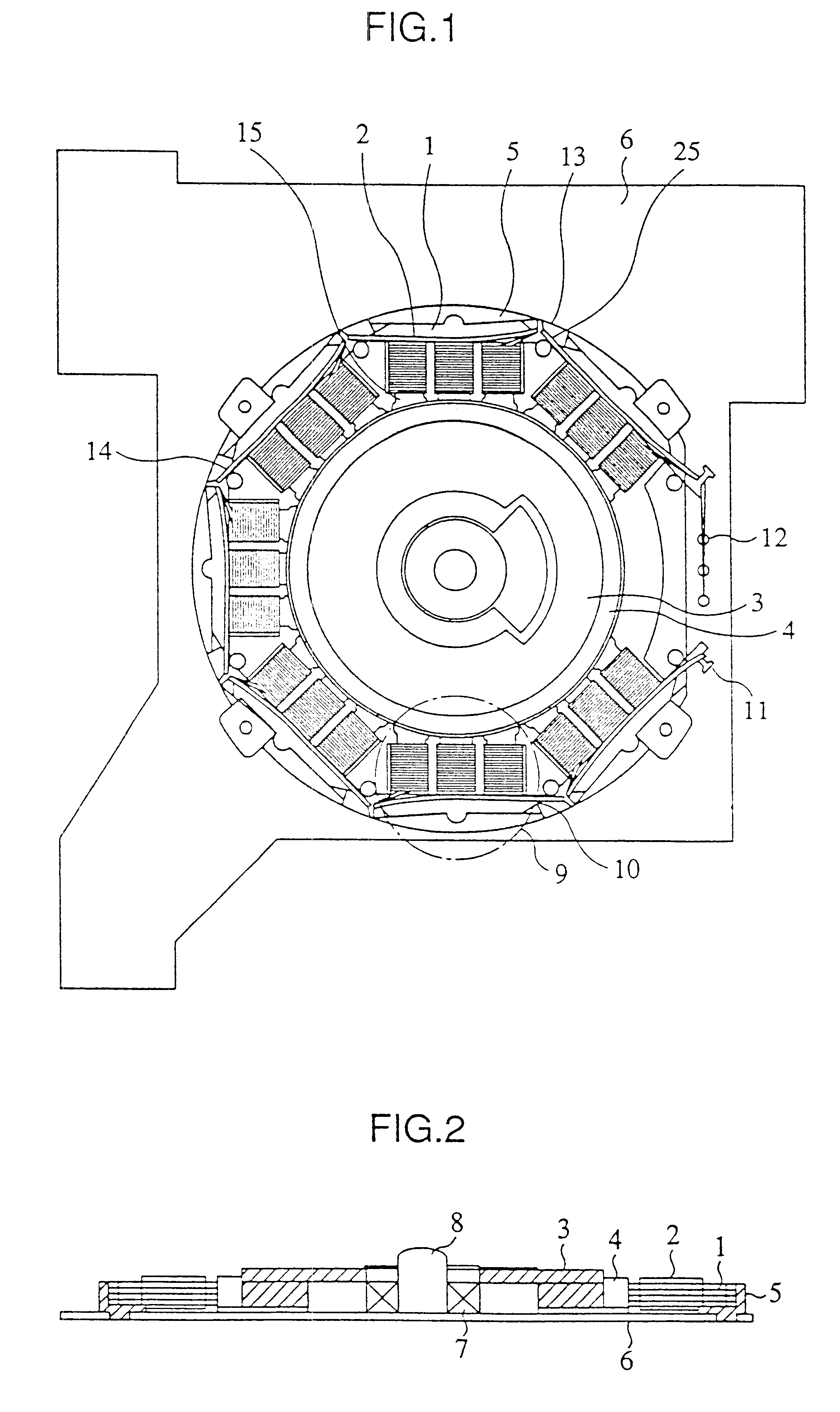
A rotary motor according to the first embodiment of the present invention will be described with reference to FIGS. 1, 2, 6 and 7. FIG. 6 shows a connecting stator core 20 which is formed by punching magnetic material by means of press. In the connecting stator core 20, the same number of magnetic teeth as the number of the phase of the motor are composed as a single block. A plurality of blocks of the connecting stator cores 20 are connected by means of thin portions 10. In producing the stator, some pieces of the connecting stator cores 20 are stacked and then subjected to insulation processing by coating or the like. Next, stacked connecting stator cores 20 i.e. a laminated core is wound with wires. That is, both ends of the stacked connecting stator cores 20 are held with tension applied thereto as shown in FIG. 7 and nozzles 21 of a winding machine which spouts conductive wire are turned around the magnetic teeth 15 in order to form coils. Although the magnetic pole teeth 15 of...

embodiment 2

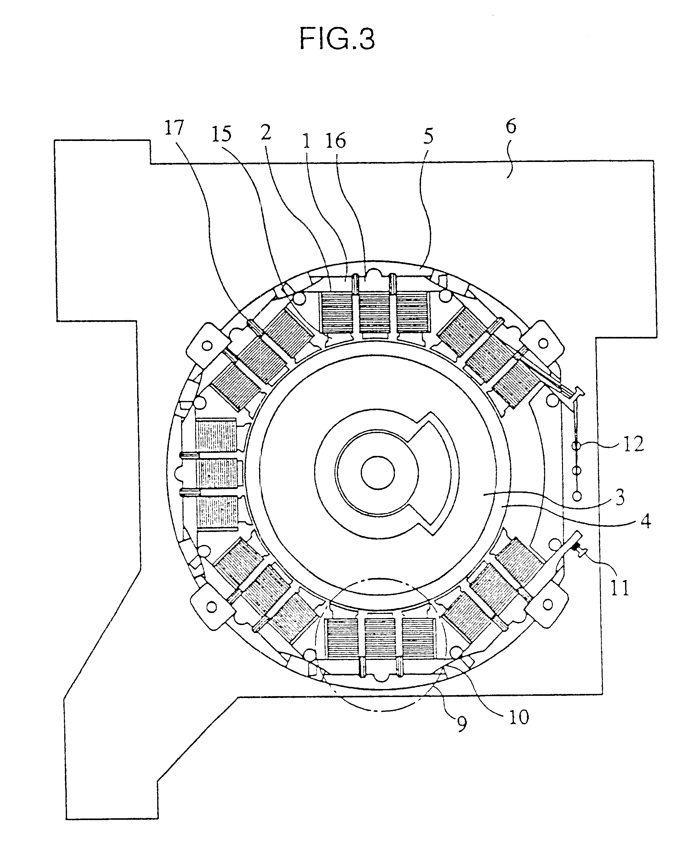
Then, the rotary motor according to the second embodiment will be explained with reference to FIGS. 3, 7. In the rotary motor of the present invention, the coil 2 is formed around the magnetic pole teeth 15 and yoke coils 17 are formed on the yoke portion 16. Thus, magnetic flux generated in the coils 2 of the magnetic pole teeth 15 flows to the yoke portion 16 as well as to the rotor 3. The yoke coil 17 is supplied with electricity to enhance the magnetic flux flowing through the yoke portion 17.

When the yoke coil 17 is wound with wire, the stacked connecting stator core 20 is turned around its longitudinal length and the wire winding nozzle 21 is used. In this case, a single wire winding nozzle 21 should be used because the yoke coil 17 is wound with wire.

embodiment 3

Then, the rotary motor according to the third embodiment will be described with reference to FIG. 4. As in the first embodiment, the stacked connecting stator core 20 is wound with wire. However, in this case, the beginning end and the terminating end of the coil are tied on part of the block. After winding of wire terminates, the tied portion is soldered to electrically connect the coil end to the stator core material of each block. As for the tying protrusion 34 on which wire is tied, in the case of three phase, three protrusions for common terminal portion 11 are provided and three protrusions for coil terminal portion 12 are provided. The three tying protrusions 34 for the common terminal portion 11 are provided on the same block 9.

When the stator is assembled, the thin portion 10 of the stator is cut without cutting the crossover wire 25 and the stator is installed to the substrate. Neutral point connection is achieved by placing three tying protrusions 34 at the same potential...


PUM


Abstract

An object of the present invention is to provide a low cost, high performance, thin structure rotary motor for driving medium used in magnetic disk drive unit, optical disk drive unit or the like, in order to improve the productivity of terminating processing and the reliability of the coils. Magnetic materials which are divided to a plurality of blocks or divided corresponding to respective magnetic pole teeth are connected by means of thin portions. The respective magnetic pole teeth are wound continuously with wire without cutting the wire at the positions in which the thin portions are connected. When a stator is assembled, a plurality of blocks or magnetic pole teeth are disposed on a substrate by separating or bending the thin portions.

Description

1. Field of the InventionThe present invention relates to the construction of a thin structure motor for driving a medium used in a magnetic disk drive unit or an optical disk drive unit, the production method thereof, and the laminated core and the production method thereof.2. Description of the Prior ArtFIG. 139 shows the stator of the spindle motor for the disk drive unit disclosed in Japanese Patent Publication No. 5-39020. The same Figure shows a stator core 20 formed integratedly by punching the magnetic material and stator coils 2 which are wound around respective teeth of the stator core 20 so that they are contained in respective slots. The spindle motor using this stator core 20 is called inner rotor type. Inside the stator, a rotor and rotor magnets are disposed so as to face the stator. The structure of the inner rotor makes it possible to form a thin structure motor and therefore is suitable for a magnetic disk drive unit and optical disk drive unit which are required t...

Claims


Application Information

Patent Timeline
IPC IPC(8): H02K3/52H02K3/46H02K1/14H02K1/18H02K15/02H02K15/095H02K15/08H02K21/14H02K3/28H02K3/18H02K29/00H02K7/14H02K5/22H02K21/22
CPCH02K1/14H02K1/146H02K1/148H02K1/185H02K3/522H02K3/524H02K11/0089H02K15/022H02K15/095H02K21/14H02K29/03H02K3/18H02K3/28H02K5/225H02K7/14H02K21/22H02K2201/06H02K2201/09H02K2201/15H02K2203/03H02K2203/06H02K2203/12H02K2211/03H02K11/40
Inventor NAKAHARA, YUJIAZUMA, KEN-ICHIMATSUMOTO, MASARUFUJITA, YOUICHIAKUTSU, SATORUHASHIMOTO, AKIRATAKAI, YASUNORIHASEGAWA, TADASHIMIYAZAKI, HIROSHIKAWADA, JUNJI
Owner MITSUBISHI ELECTRIC CORP
Why Eureka
Try Eureka