Power electronics device for controlling an electric machine

a technology of power electronics and electric machines, which is applied in the direction of electrical apparatus contruction details, motor/generator/converter stoppers, dynamo-electric converter control, etc., can solve the problems of small installation space available for electric machines, heat loss produced during operation, and limited installation spa

Inactive Publication Date: 2001-12-04
ZF FRIEDRICHSHAFEN AG
View PDF13 Cites 118 Cited by
  • Summary
  • Abstract
  • Description
  • Claims
  • Application Information

AI Technical Summary

Problems solved by technology

When an electric machine is used in a vehicle, installation space is limited.
Therefore, only a small installation space is available for the electric machine and the components required for operating the electric machine including a power electr

Method used


Image

  • Power electronics device for controlling an electric machine
  • Power electronics device for controlling an electric machine
  • Power electronics device for controlling an electric machine

Examples


Embodiment Construction

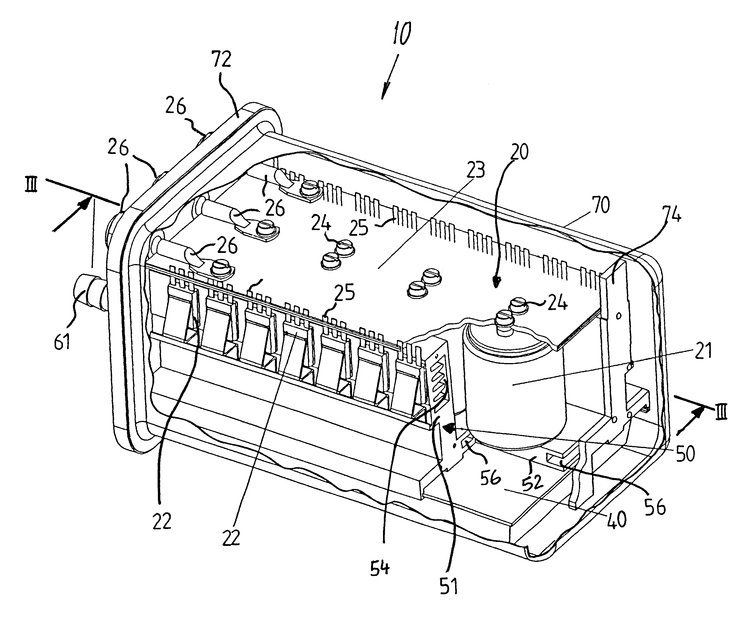
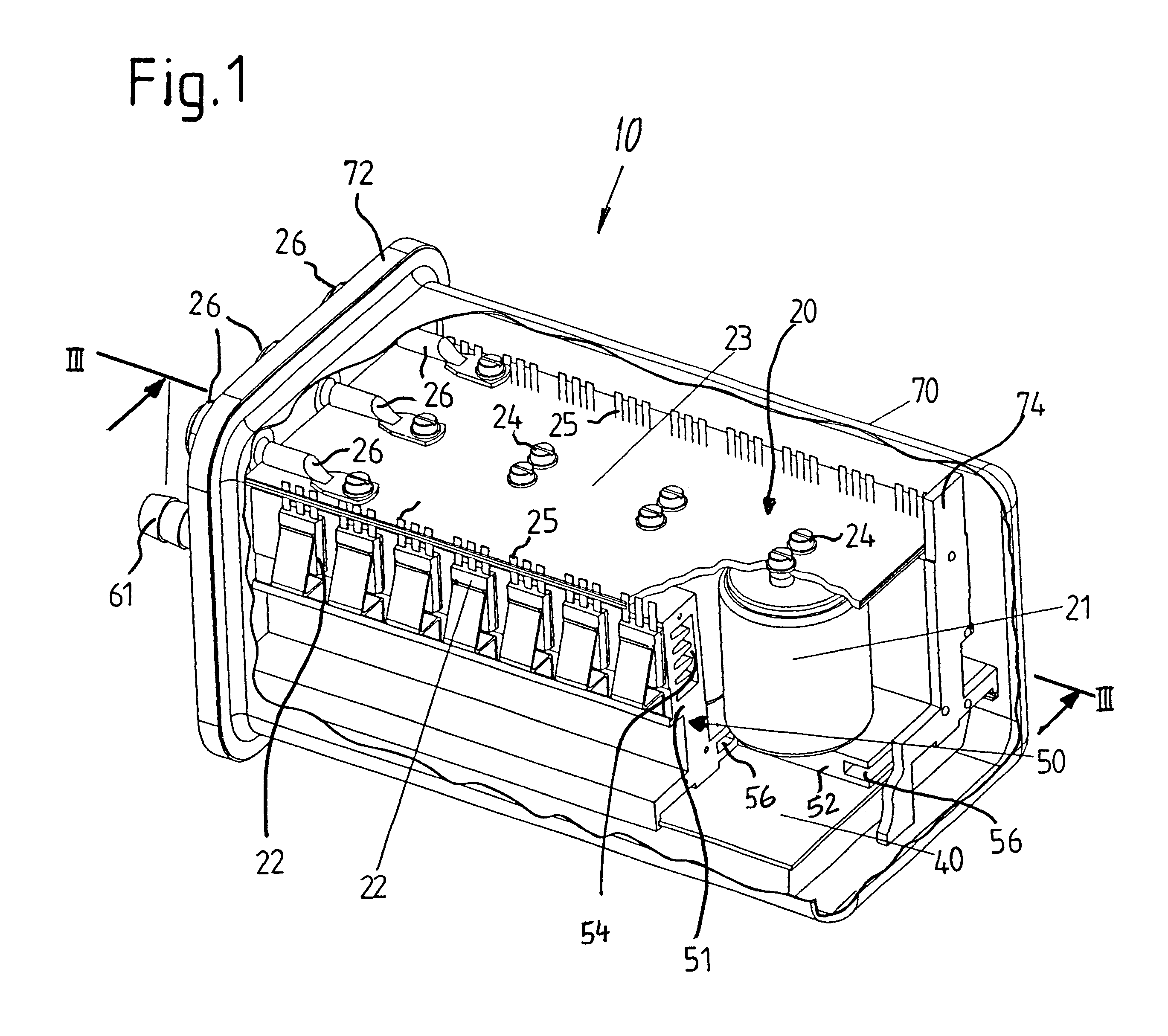
FIGS. 1 to 5 illustrate a power electronics device 10 according to an embodiment of the present invention for controlling an electric machine comprising a starter-generator for a motor vehicle and constructed as a permanently excited synchronous machine.

FIG. 1 shows a housing 70 for the power electronics device 10 which is produced as a deep-drawn aluminum part. The housing 70 is closed on all sides apart from a housing opening 71 (see FIG. 3) at one end. A cover element 72 is used to close the housing opening 71 and is detachably connected to the housing 70. The cover element 72 has a number of openings 73 (see FIG. 4), through which a number of connecting elements may be led. The cover element 72 thus functions as a connecting board for the power electronics device 10.

FIG. 5 shows that the connecting elements include five electrical power connecting elements 26. Referring now to FIGS. 1 and 2, the electrical power connecting elements 26 are connected to a power section 20 of the p...


PUM


Abstract

A power electronics device for controlling an electric machine including a power section arranged within a housing which can be closed via a cover element. The power section has a plurality of capacitors and a plurality of power semiconductors which are connected to a power bus bar. In addition, a control device is provided for controlling the power electronics device. The capacitors, power semiconductors, and control device are cooled via a cooling device which is formed as a profile having an essentially U-shaped cross section. The cooling device has two lateral limbs and a base region through which cooling ducts are arranged. A suitable cooling medium flows through the cooling ducts and the ends of the cooling ducts opposite the housing cover are closed by a covering element. The capacitors, the power semiconductors and the control device are connected to the cooling device such that thermal exchange occurs between these components and the cooling device.

Description

1. Field of the InventionThe present invention relates to a power electronics device for controlling an electric machine.2. Description of the Related ArtElectric machines comprise a wide variety of machines for converting energy from one form to another and include generators and motors. Among the many types of electric machines, synchronous machines are used for generating electrical energy. The electrical energy generated by the synchronous machine may then be applied to an extremely wide range of loads. These loads are usually combined into electrical networks which may, for example, comprise an on-board electrical network for a vehicle. When an electric machine is used in a vehicle, installation space is limited. Therefore, only a small installation space is available for the electric machine and the components required for operating the electric machine including a power electronics device. Accordingly, the individual components are required to be as compact and space-saving a...

Claims


Application Information

Patent Timeline
IPC IPC(8): H05K7/20
CPCH02M7/003
Inventor TAREILUS, ALFRED
Owner ZF FRIEDRICHSHAFEN AG
Why Eureka
Try Eureka