Radiogram showing location of automatic exposure control sensor

a technology of automatic exposure control and radiograph, which is applied in the field of electronic radiography, can solve the problems of excessive quantum noise (mottle) in the image, unnecessarily high radiation dose to the patient, and possible saturation of the detector,

Inactive Publication Date: 2001-12-04
DIRECT RADIOGRAPHY
View PDF11 Cites 113 Cited by
  • Summary
  • Abstract
  • Description
  • Claims
  • Application Information

AI Technical Summary

Problems solved by technology

If the time is too long the results will be unnecessarily high radiation dose to the patient and possible saturation of the detector.
If the time is too short, the results will be lack of detail in certain areas, as well as excessive quantum noise (mottle) in the image.
In some cases the radiographic examination may need to be repeated, exposing the patient to additional radiation, as well as delaying the evaluation of the examination results and increasing the cost of the procedure.
A problem with most prior art systems that rely on intensity integration is that the intensity of the radiation incident on the control sensor depends on the relative position of the patient and the sensor.
If it is intended that th

Method used


Image

  • Radiogram showing location of automatic exposure control sensor
  • Radiogram showing location of automatic exposure control sensor
  • Radiogram showing location of automatic exposure control sensor

Examples


Embodiment Construction

)

Throughout the following detailed description, similar reference characters refer to similar elements in all figures of the drawings.

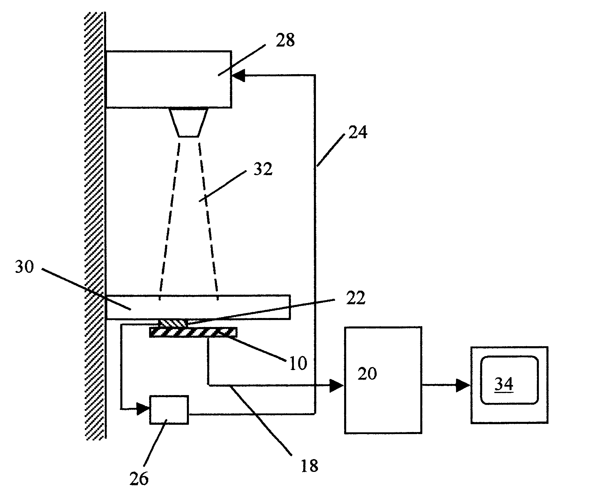
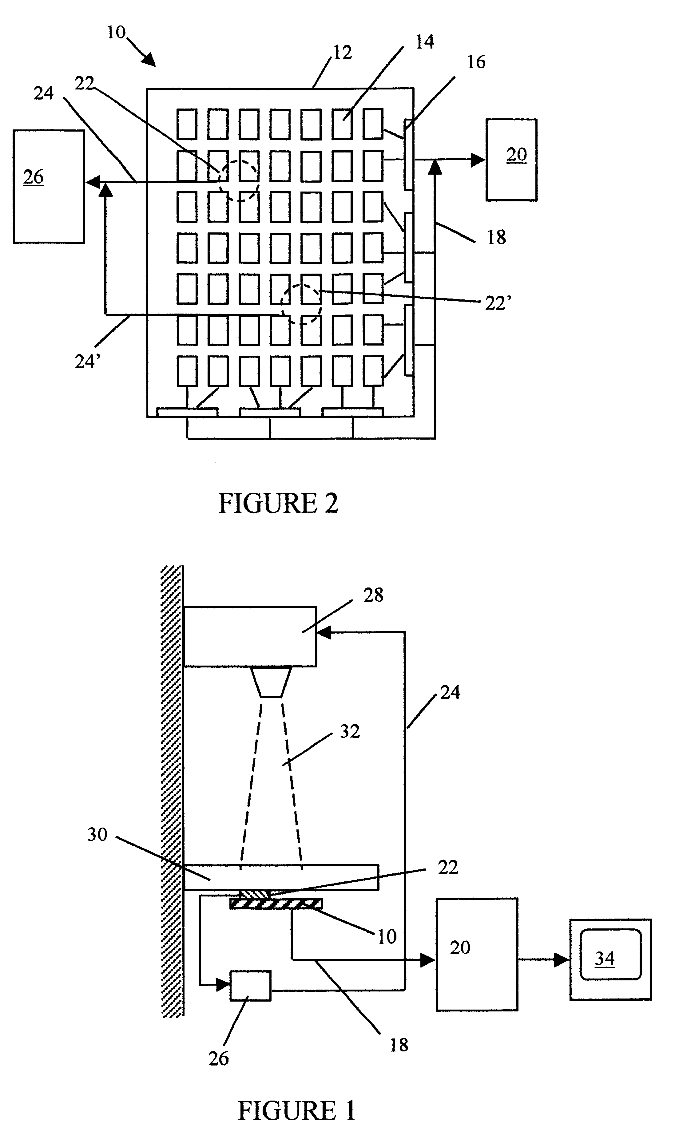
Referring now to FIG. 1, there is shown a typical radiographic installation for obtaining an electronic radiogram of a patient. The system typically includes a radiation source and a patient support table 30. The radiation source 28 emits on command x-rays as an x-ray radiation beam 32 directed toward a predetermined area of the table 30. Beneath the table 30 in the area where the radiation beam 32 is directed, there is an imaging panel 10. The imaging panel comprises a plurality of individual radiation detectors each corresponding to one picture element, typically arrayed in a two dimensional array. The array of sensors forms an image sensitive area over which a subject to be examined is placed.

The imaging panel 10 usually includes along at least one edge thereof a plurality of electronic components for addressing each individual sensor in the panel,...


PUM


Abstract

A method for optimizing the radiogram image of a subject is provided. The method provides for showing the location of automatic exposure control sensors on the radiograms, along with alignment and targeting projections to optimize the radiation exposure of the subject. By displaying the location of the automatic exposure control sensors on the radiograms along with the image of the subject, the observers can determine whether the radiogram image was taken with appropriate subject alignment. This method also serves as an educational aid in training radiography technicians.

Description

1. Field of the InventionThis invention relates to electronic radiography and more particularly to automatic exposure control systems and methods.2. Description of Related ArtElectronic radiographic imaging, also commonly referred to as direct radiographic imaging, using imaging panels comprising a two dimensional array of minute sensors to capture a radiation generated image is well known in the art. Information representing an image is captured, usually as a charge distribution stored in a plurality of charge storage capacitors, in individual sensors arrayed in a two dimensional matrix. Readout of the stored charges provides an electrical signal which may be used to display the captured charges as a radiographic image on a display device, such as a cathode ray tube.In a typical arrangement, an X-ray radiation source is used to provide a radiation beam. The radiation beam is aimed at an imaging panel at a known and usually fixed position, spaced from the source. A patient is positi...

Claims


Application Information

Patent Timeline
IPC IPC(8): A61B6/08H05G1/00H05G1/36
CPCA61B6/08A61B6/4233A61B6/542H05G1/36
Inventor GINGOLD, ERICMERELLO, JAMES K.POWELL, GREGORY F.
Owner DIRECT RADIOGRAPHY
Why Eureka
Try Eureka