Valve timing control system for internal combustion engine

Inactive Publication Date: 2001-12-11
UNISIA JECS CORP
View PDF14 Cites 43 Cited by
  • Summary
  • Abstract
  • Description
  • Claims
  • Application Information

AI Technical Summary

Problems solved by technology

However, this improvement requires the

Method used


Image

  • Valve timing control system for internal combustion engine
  • Valve timing control system for internal combustion engine
  • Valve timing control system for internal combustion engine

Examples


first embodiment

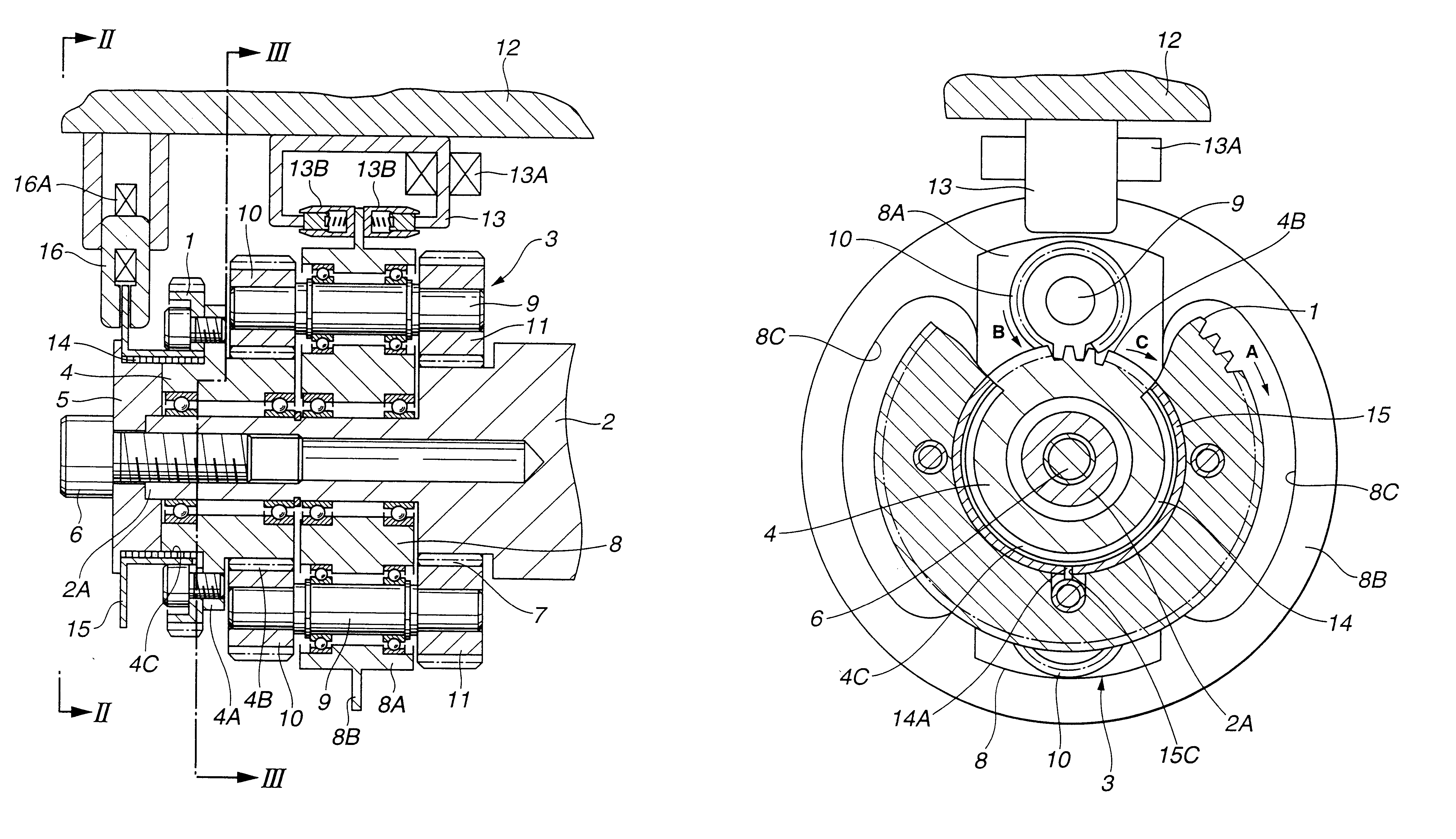
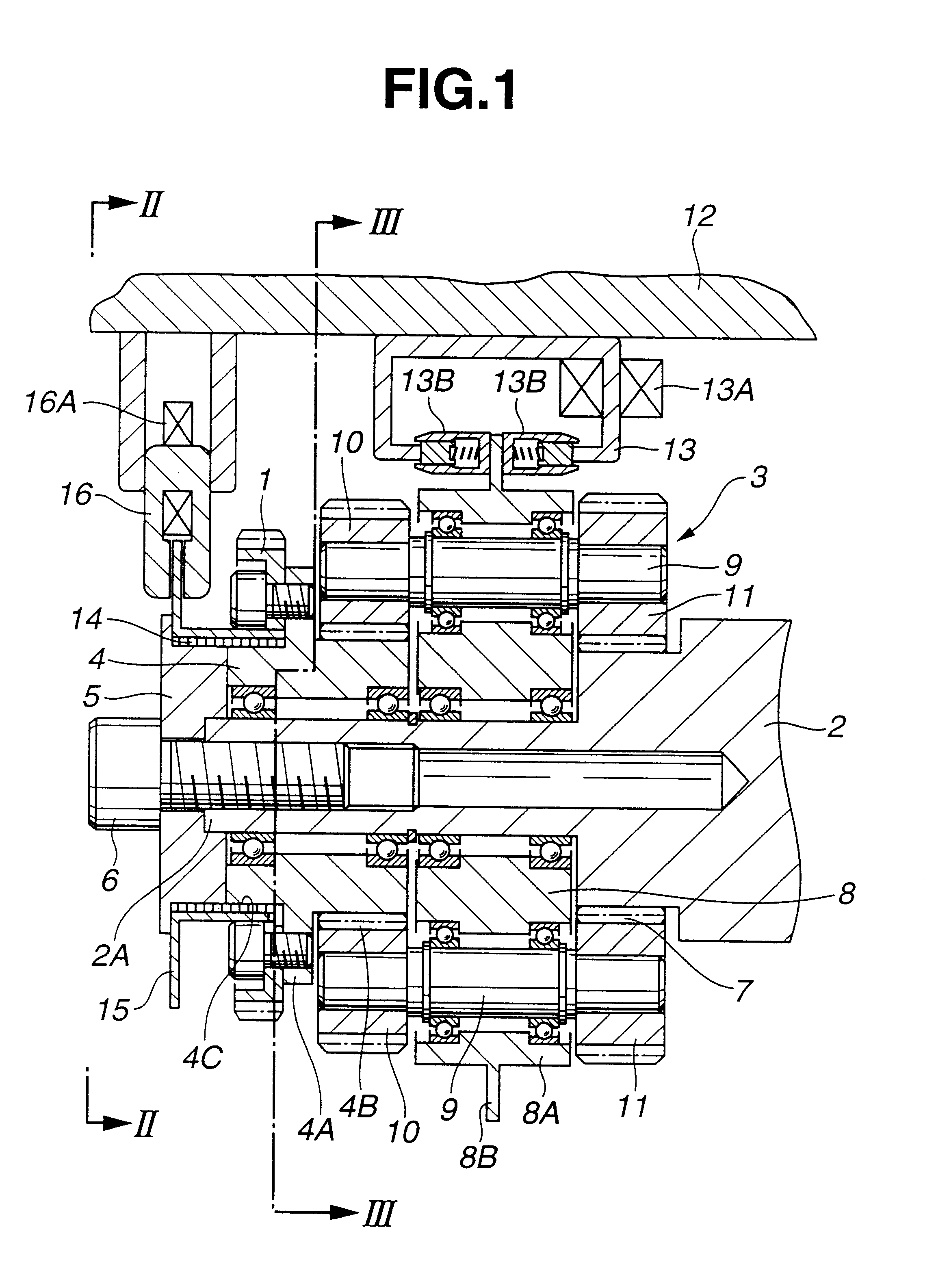
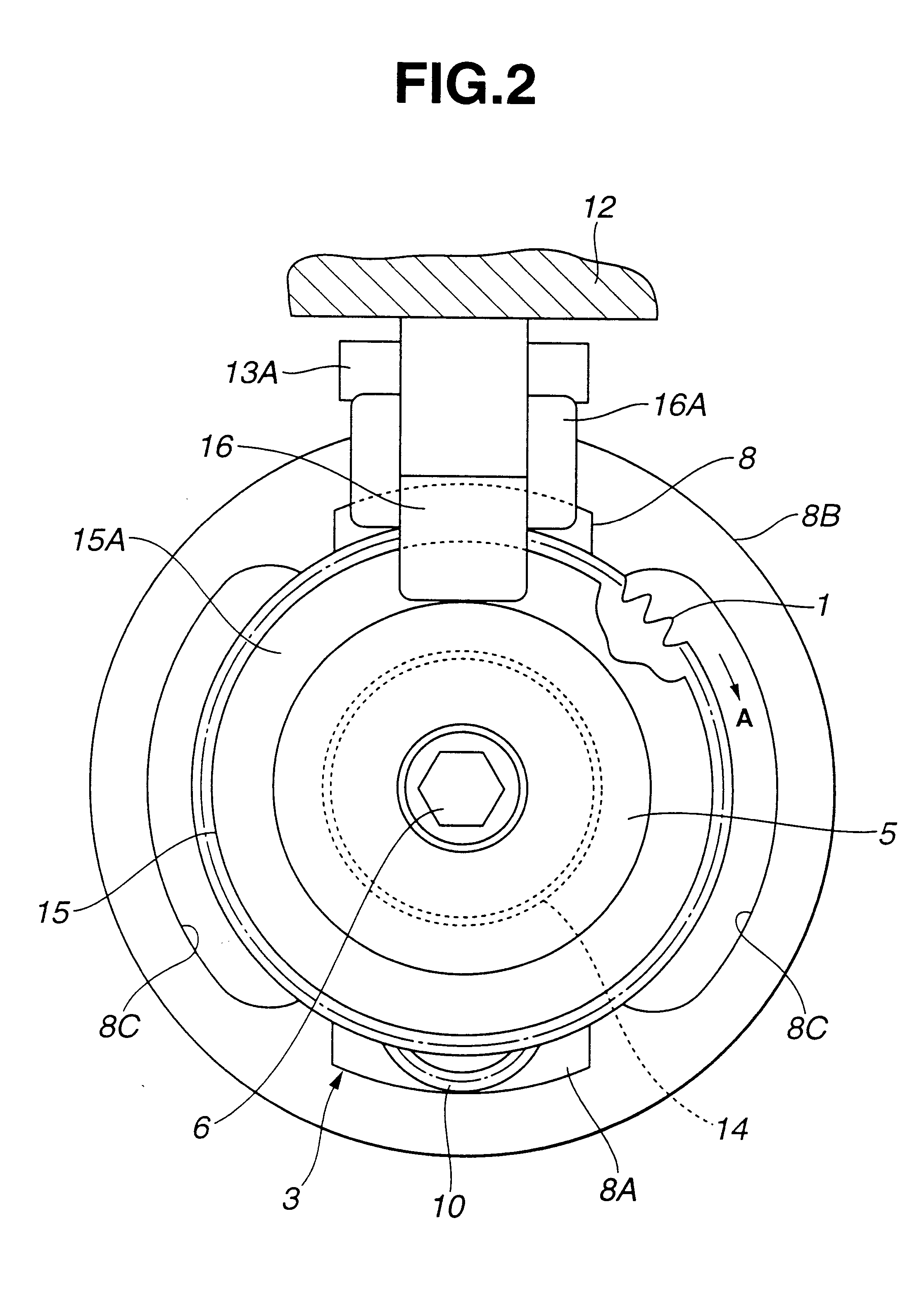
FIGS. 1 through 6 show the valve timing control system, according to the present invention.

A driven sprocket 1 acting as a rotor is connected to a crank shaft (not shown) of the internal combustion engine via a timing belt (not shown). The driven sprocket 1 is rotated by the crankshaft in a direction A (clockwise) in FIG. 2 around a camshaft 2.

The camshaft 2 is rotatably disposed on a cylinder head (not shown) of the internal combustion engine. In accordance with the rotation of the driven sprocket 1, the camshaft 2 is also rotated in the direction A in FIG. 2. The camshaft 2 acts to open and close either one of or both of intake valve and exhaust valves (not shown) of the internal combustion engine. The camshaft 2 has a small diameter portion 2A and an external gear 7. The small diameter portion 2A is located at an endmost portion of the camshaft 2 as shown in FIG. 2. Around an outer periphery of the small diameter portion 2A, there are rotatably disposed an input gear member 4 and...

second embodiment

The second embodiment ensures operations and advantages substantially the same as those of the first embodiment. Disclosed below are specifics about the operations and the advantages of the present invention.

At first, when the brake control coil 33A of the solenoid brake 33 is demagnetized as is seen in Table 2 and when the driven sprocket 21 rotates in the direction A (clockwise) in FIG. 8, the rotation of the driven sprocket 21 is transmitted from the external gear 26C of the input gear member 26 to the first planet gears 30. The first planet gears 30 rotate on the planet shafts 29 and revolve around the input gear member 26. The revolving force of the first planet gears 30 is transmitted to the carrier 28 as a rotational torque.

Under this condition, the first spring clutch 34 receives the torsional torque in the direction to increase its coil diameter under the torque condition satisfying Expression (3). With this, the first spring clutch 34 is slightly spaced apart from the oute...

third embodiment

The third embodiment ensures operations and advantages substantially the same as those of the first embodiment. Disclosed below are specifics about the operations and the advantages of the present invention.

At first, when the brake control coil 63A of the solenoid brake 63 is demagnetized as is seen in Table 3 and when the driven sprocket 51 rotates in the clockwise direction, the rotational force of the driven sprocket 51 is transmitted from the internal gear 57A of the input gear member 57 to the first planet gears 61. With this, the first planet gears 61 rotate on the planet shaft 60 and revolve along the input gear member 57. The revolving force of the first planet gears 61 is transmitted to the carrier 59 as a rotational torque.

In this condition, the first spring clutch 64 receives the torsional torque in the direction to increase its coil diameter under the torque condition satisfying Expression (7). Therefore, the first spring clutch 64 is slightly spaced apart from the outer...


PUM


Abstract

A valve timing control system includes; a rotor rotated by a crankshaft of the internal combustion engine; a camshaft rotated according to the rotation of the rotor to open and close an intake valve and an exhaust valve of the internal combustion engine; and a rotational phase controller for variably controlling a rotational phase of the camshaft relative to the rotor. The rotational phase controller is disposed between the rotor and the camshaft. The rotational phase controller includes; a clutch selectably put in one of a holding state for forbidding a relative rotation between the rotor and the camshaft in at least one of rotational directions and a releasing state for allowing the relative rotation; and a generator for generating a holding toque directing to the rotational direction forbidden by the clutch and applying the holding torque to the clutch when the clutch is put in the holding state.

Description

1. Field of the InventionThe present invention relates to a valve timing control system for varying valve timing of intake and exhaust valves of an internal combustion engine for a motor vehicle according to a vehicle driving condition.2. Description of the Related ArtVarious valve timing control systems have been proposed and in practical use for the purpose of further improving performance of internal combustion engines. Japanese Patent Unexamined Publication No. 5(1993)-1514 discloses a typical valve timing control system which employs a pair of spring clutches and a selector for switching operation of the spring clutches. This conventional valve timing system is arranged to vary the valve timing by controlling a phase varying device installed between a sprocket and a camshaft. The phase varying device for preferably varying the valve timing into an advanced state or retarded state as shown in FIG. 30 has a pair of spring clutches coaxial with the camshaft and a clutch switching ...

Claims


Application Information

Patent Timeline
IPC IPC(8): F01L1/00F01L1/344F01L1/352F01L1/34F01L1/46F02D13/02F16D27/105F16D55/224
CPCF01L1/34F01L1/352F01L1/46Y10T74/2102F01L2001/34453
Inventor IO, SHINICHI
Owner UNISIA JECS CORP
Why Eureka
Try Eureka