Phase locked loop arrangement in which VCO frequency is a fraction of reference frequency
a phase lock and loop technology, applied in oscillation comparator circuits, automatic control of pulses, instruments, etc., can solve the problems of increasing the complexity of the arrangement, unable to address the problem of phase noise, and increasing the phase noise of the output signal
- Summary
- Abstract
- Description
- Claims
- Application Information
AI Technical Summary
Benefits of technology
Problems solved by technology
Method used
Image
Examples
first embodiment
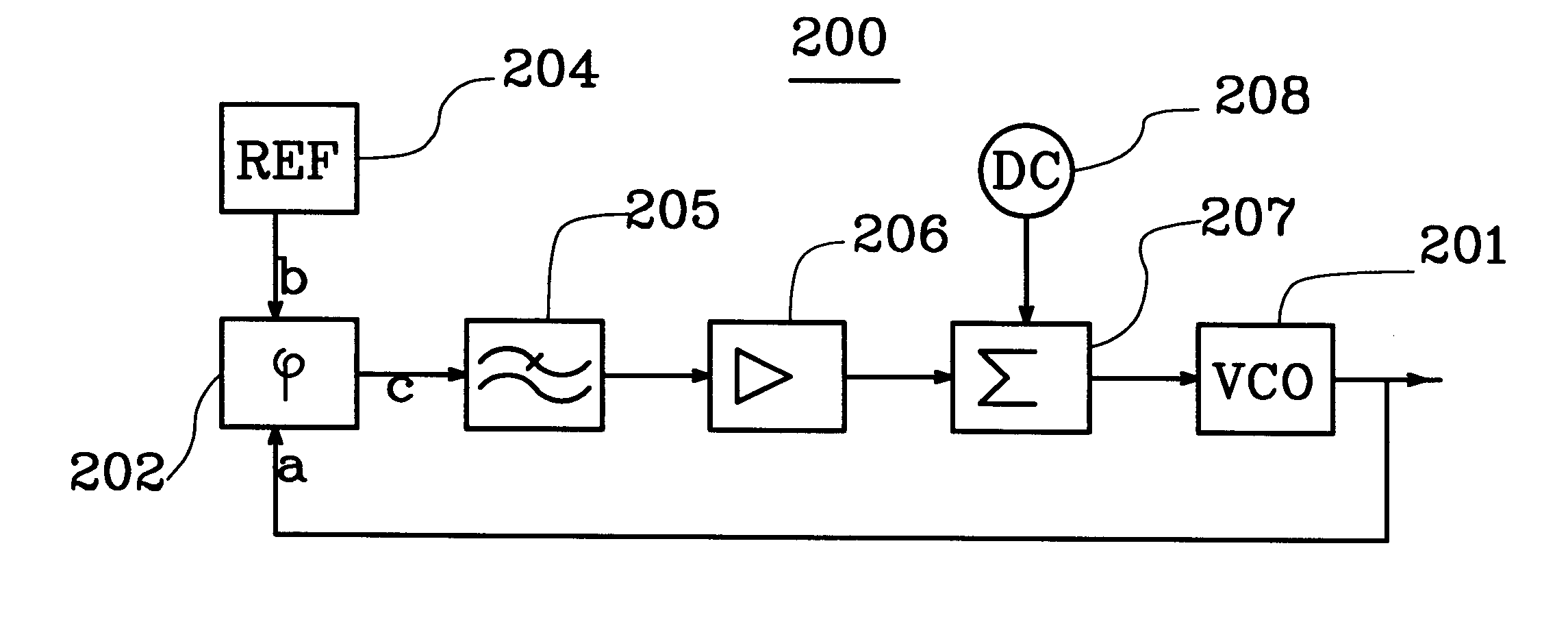
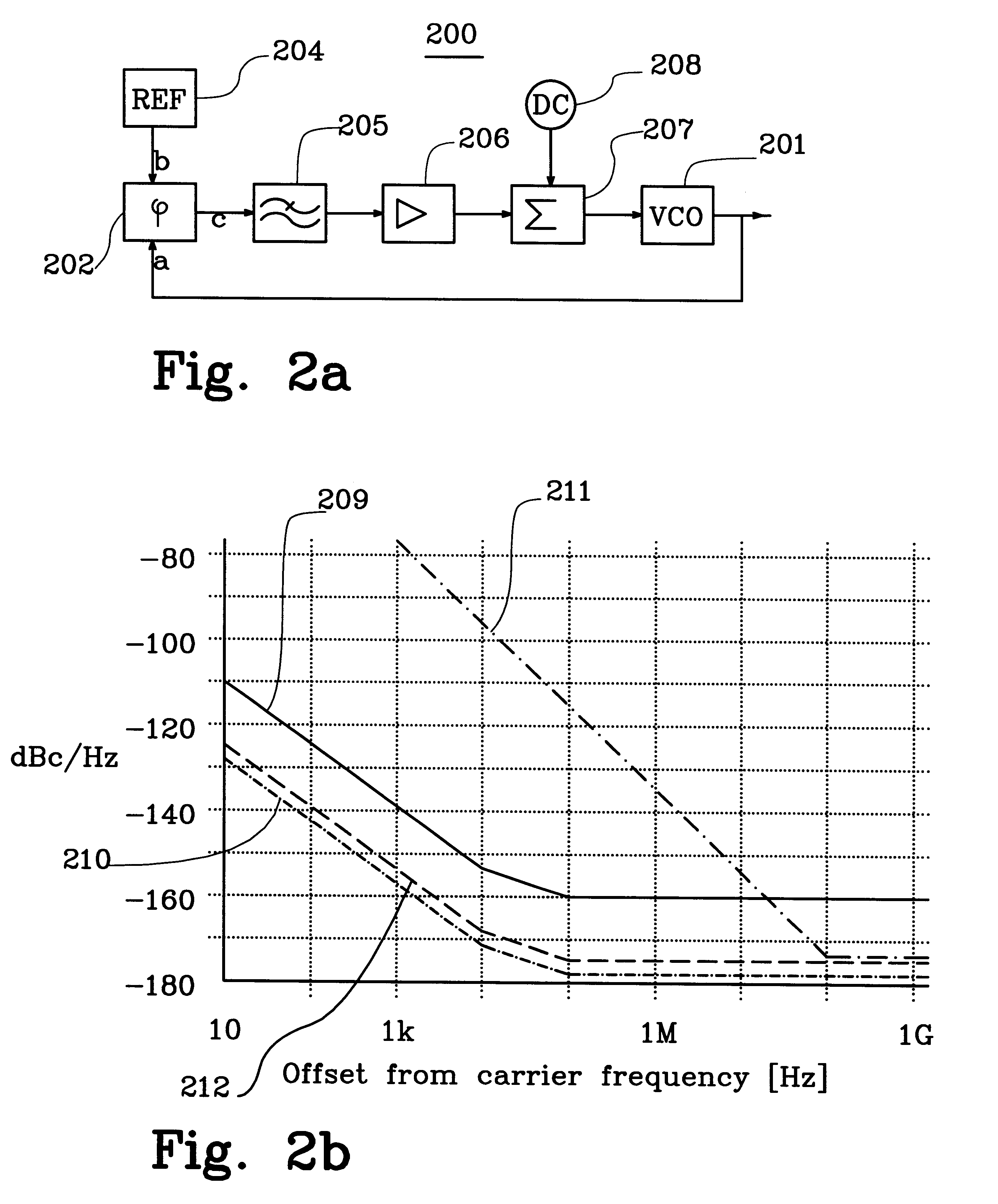
the phase detector means is illustrated in FIG. 3. The phase detector means is then formed by a sample and hold circuit 301. The sample and hold circuit functions in the following manner. Each time the VCO output signal inputted at input (a) reaches a certain stage in its cycle, the input voltage at input (b) is sampled and thus appears on the output (c). The output voltage is then kept constant until a new sample is retrieved. Thus, the VCO signal samples the reference signal. The state of the input signal (a) triggering the sample procedure may preferably be a zero-crossing with positive or negative direction of the voltage. A peak voltage may, however, also be used. It is of course also possible to trigger sample procedures more than one time per cycle, for instance twice a cycle at all zero crossings. Note that the signal appearing at input (a) has a lower frequency than the signal appearing at input (b) . In this embodiment, the output frequency of the frequency synthesiser may...
second embodiment
the phase detector means is illustrated in FIG. 4. The phase detector means 401 is then formed with a frequency multiplier circuit 402. Such a multiplier is a standard component and multiplies the frequency of the incoming signal at (a) with a certain fixed factor. The multiplier 402 may optionally be devised to provide two or more different factors by using selectable modules 403, 404, in the depicted embodiment with factors 3 and 7. The signal thus multiplied is coupled to a mixer 405. The mixer mixes the signal outputted from the reference oscillator and received at input (b) and having a frequency f.sub.1 with a signal from the frequency multiplier now having a frequency f.sub.2. The mixer outputs a signal containing the frequency components f.sub.1 +f.sub.2 and f.sub.1 -f.sub.2. The component with the frequency f.sub.1 +f.sub.2 is then outside the bandwidth of the loop filter. The component with the frequency f.sub.1 -f.sub.2 on the other hand is an error signal that regulates ...
third embodiment
the phase detector means 501 is illustrated in FIG. 5. The signal from the VCO received at a first input (a) is then applied to a so called comb unit 502, which accomplishes a number of harmonics to the VCO output signal. One or some of those harmonics are selected by means of a variable bandpass filter 503 and is applied to a mixer 504, which functions similarly to the mixer of the embodiment described in FIG. 4.
PUM
 Abstract
Description
Claims
Application Information
 - R&D
- Intellectual Property
- Life Sciences
- Materials
- Tech Scout
- Unparalleled Data Quality
- Higher Quality Content
- 60% Fewer Hallucinations
Browse by: Latest US Patents, China's latest patents, Technical Efficacy Thesaurus, Application Domain, Technology Topic, Popular Technical Reports.
© 2025 PatSnap. All rights reserved.Legal|Privacy policy|Modern Slavery Act Transparency Statement|Sitemap|About US| Contact US: help@patsnap.com


