Compressed-air landing strut and method for its manufacture

Inactive Publication Date: 2002-01-08
CONTINENTAL AG
View PDF17 Cites 28 Cited by
  • Summary
  • Abstract
  • Description
  • Claims
  • Application Information

AI Technical Summary

Benefits of technology

to create an attachment of a pneumatic shock absorber to a spring support which is easy to manufacture and whic

Problems solved by technology

However, it is evident that the compressed air landing strut known from the aforementioned publications must first be fully assembled

Method used


Image

  • Compressed-air landing strut and method for its manufacture
  • Compressed-air landing strut and method for its manufacture
  • Compressed-air landing strut and method for its manufacture

Examples


Example

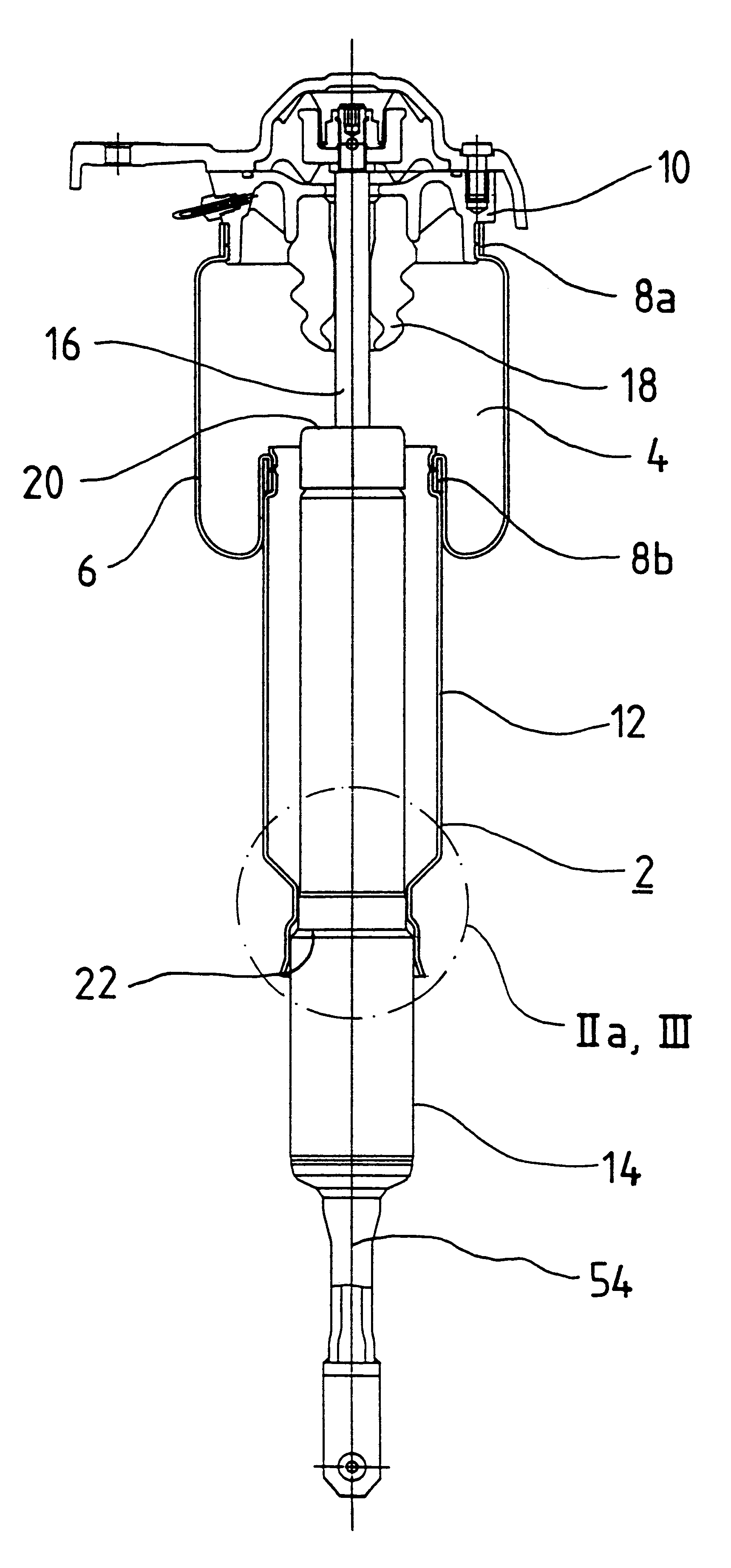
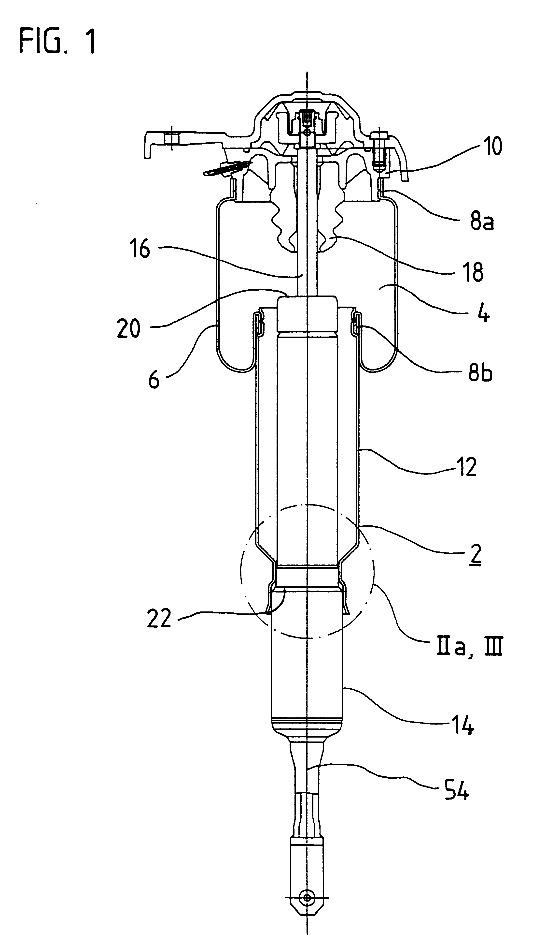
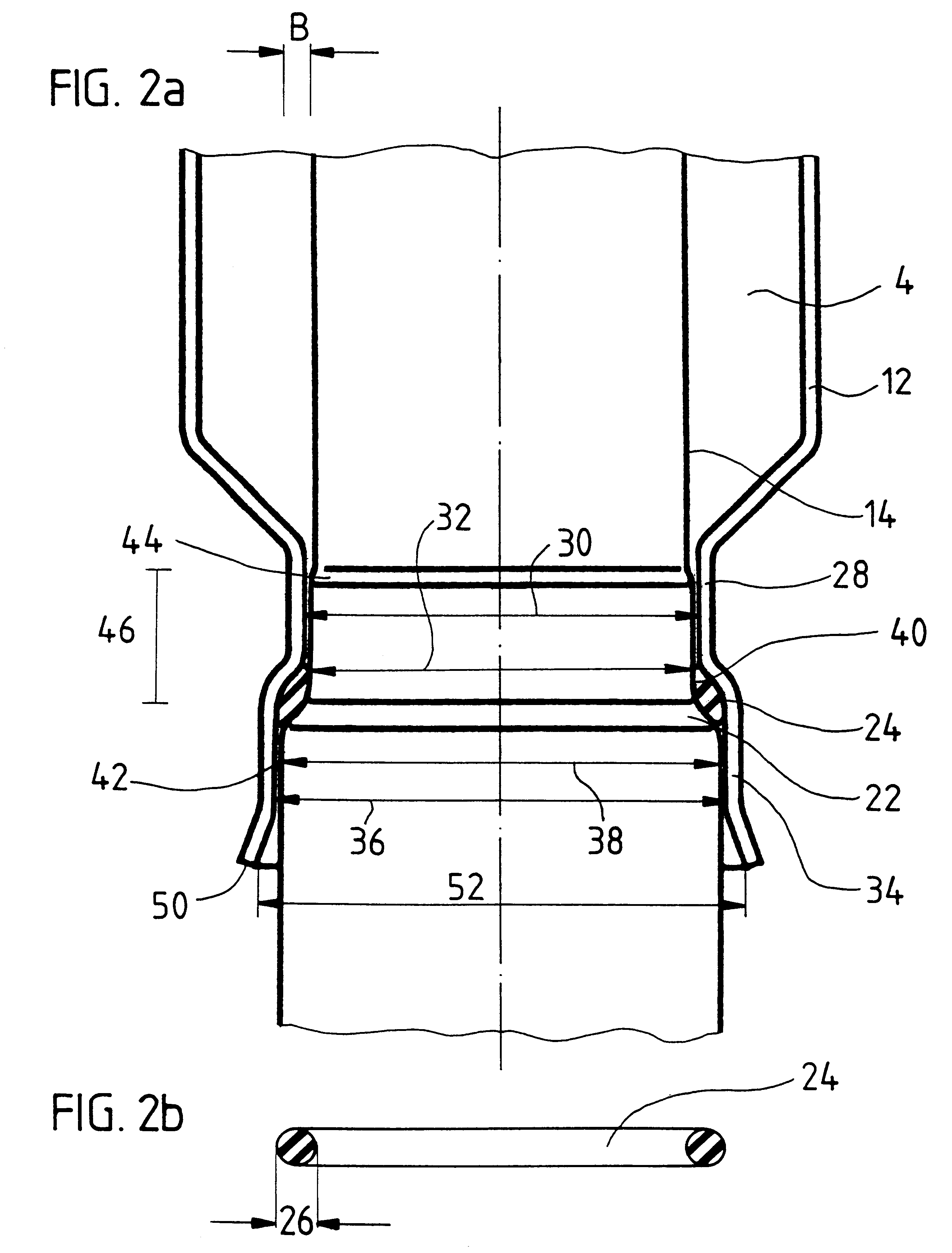
The advantages achieved with the present invention can be seen, in particular, by the fact that the attachment of the roll-off piston to the spring support is established in a simple manner, since we need merely an easily manufactured O-ring, available as an off-the-shelf part, which is placed on the offset of the spring support. In addition, due to the radial compression of the O-ring between the outer wall of the spring support and the inner wall of the roll-off piston, an air-tight seal against the environment is ensured for the spring space surrounding the pneumatic shock absorber. An additional advantage of the invention is that both the outer wall of the spring support in the region of the recess, and also the end region of the roll-off piston facing the spring support, can have certain manufacturing tolerances, since these are compensated by the high radial compression of the O-ring, and thus the air-tight sealing of the spring space against the environment is not adversely a...


PUM


Abstract

A compressed air landing strut 2 is disclosed with a pneumatic shock absorber which is set onto a spring support 14. The spring support 14 has an offset 22 and the end region 24 of the roll-off piston 12 is flared radially outward, so that it surrounds the offset 22. An O-ring 24 is radially compressed between the outer wall 40 of the spring support 14 and the inner wall 42 of the roll-off piston 12 and seals the spring space 4 of the pneumatic shock absorber air-tight against the environment. A method for the manufacture of said pneumatic shock absorber is also disclosed.

Description

INTRODUCTION AND BACKGROUNDThe present invention pertains to a compressed air landing strut which contains the following components:a pneumatic shock absorber with rolling bellows which enclose a spring spacea roll-off piston along which the rolling bellows can rolla spring support that is immersed in the roll-off piston, with an offset in which the roll-off piston is braceda ring-shaped gasket which is located between the spring support and the roll-off piston and seals the spring space against the environment.A compressed air landing strut of the kind specified above is known, for example, from German 44 28 601 A1. The compressed air landing strut contains a pneumatic shock absorber with an outer tube which, together with a rolling bellows and a roll-off piston, surrounds a spring space. The roll-off piston of the pneumatic shock absorber is braced on an offset of the spring support, which can be designed, for example, as a shock absorber. Above the offset of the spring support th...

Claims


Application Information

Patent Timeline
IPC IPC(8): B60G15/12B60G15/00F16F9/02F16F9/05F16F9/084F16F9/00F16F9/08F16J15/06
CPCB60G15/12F16F9/084F16F9/05
Inventor WODE, STEFAN
Owner CONTINENTAL AG
Why Eureka
Try Eureka