Method and apparatus for improved EAF steelmaking

a technology of eaf steelmaking and methods, applied in the direction of manufacturing converters, combustion types, furnaces, etc., can solve the problems of reducing the efficiency of eaf steelmaking, and reducing the difficulty of eaf steelmaking

Inactive Publication Date: 2002-01-29
PROCESS TECH INT
View PDF5 Cites 58 Cited by
  • Summary
  • Abstract
  • Description
  • Claims
  • Application Information

AI Technical Summary

Problems solved by technology

A straight conduit is conventional because the particulates injected into a steel making furnace are highly abrasive and will wear out bends or other restrictions to their flow quickly.
This is one of the reasons why particulates have not be injected through the same conduit as the one used for supersonic oxygen of a burner, the particulates would quickly wear out the converging restriction of the nozzle.
A central conduit is preferred because it is highly disadvantageous to break the

Method used


Image

  • Method and apparatus for improved EAF steelmaking
  • Method and apparatus for improved EAF steelmaking
  • Method and apparatus for improved EAF steelmaking

Examples


Embodiment Construction

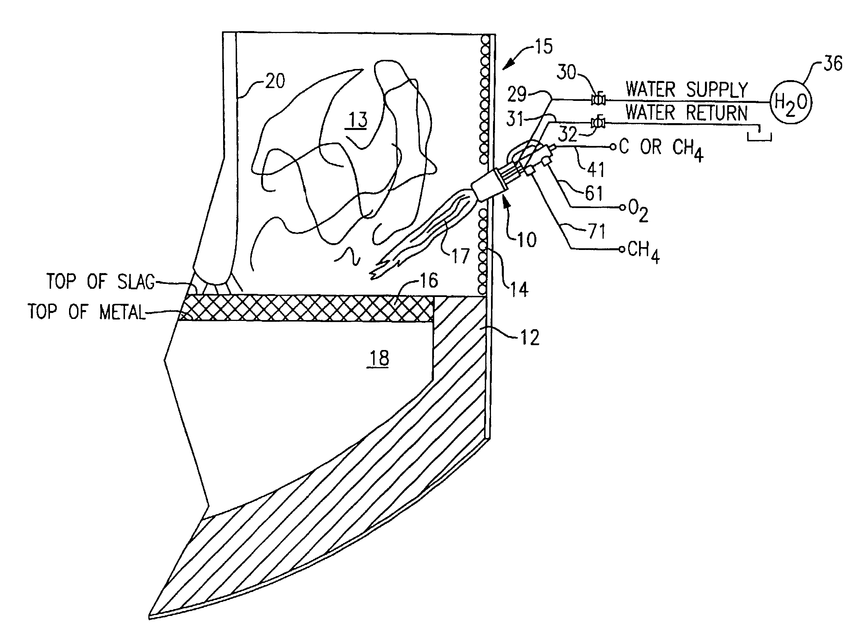
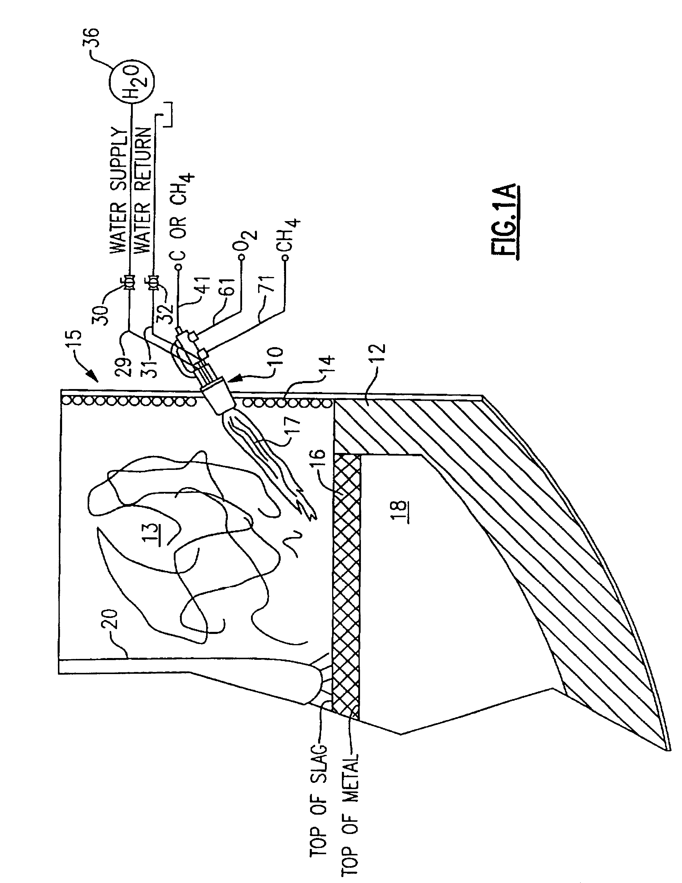
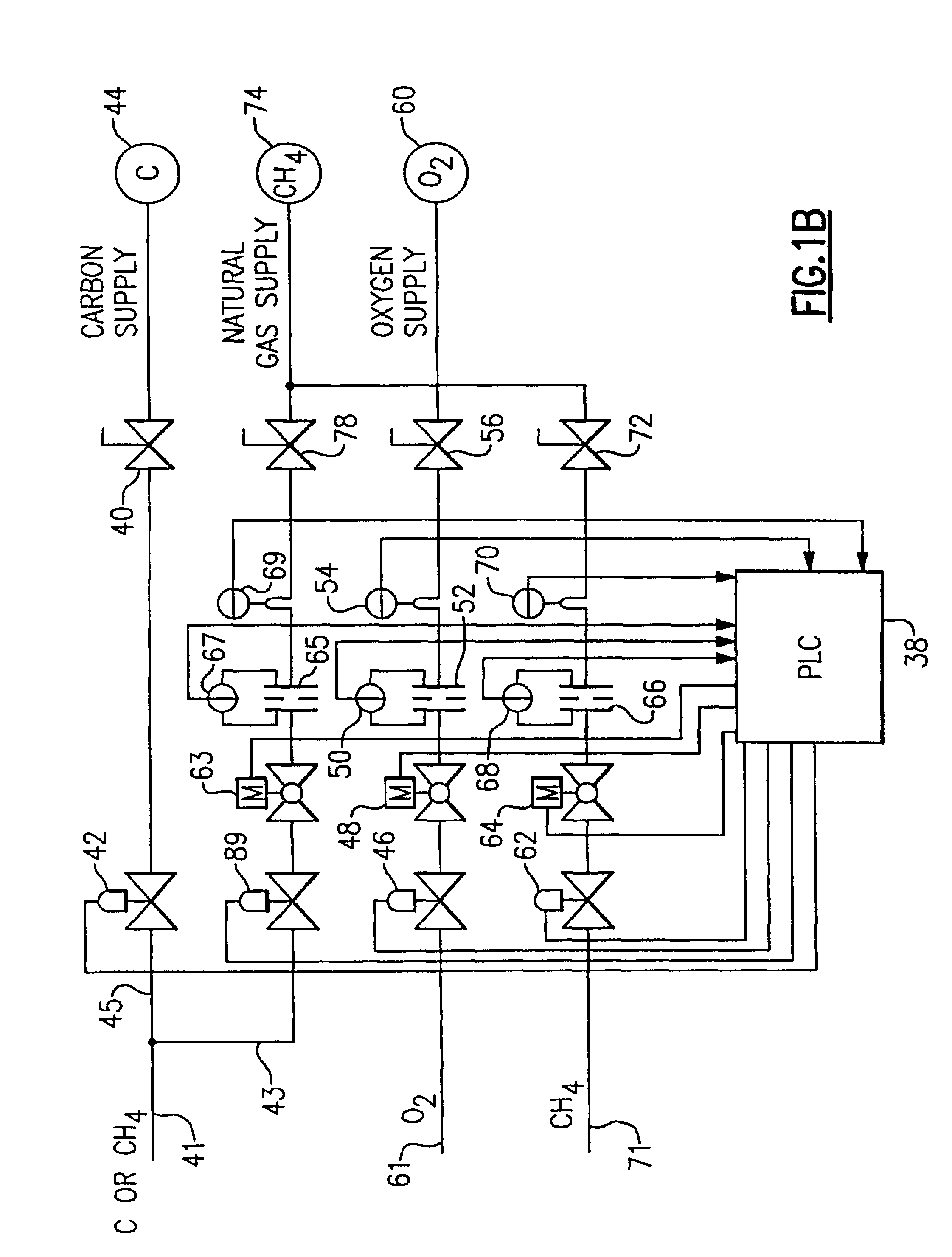
A burner 10 which is capable of operating in several different modes to provide either additional thermal energy, metal refining and / or other metallurgical processing capabilities in an electric arc furnace (EAF) 15, or other process furnace, is shown to advantage in FIGS. 1A and B. The EAF 15 conventionally melts ferrous scrap 13, or other ferrous materials, by means of an electric arc produced from one or more electrodes 20 to produce a molten metal melt 18 at its bottom. One or more of the burners 10 may assist in the process by providing additional thermal energy to melt the scrap faster. The iron melt 18 is generally covered with various amounts of slag 16 which is produced during the process of melting the metal from additives to the process.

The burner 10 is preferably mounted in the side wall 12 of the shell of the EAF 15 through an aperture in the fluid cooling elements 14 of the wall of the furnace and inclined downward at an angle to direct a flame 17, or other injected ma...


PUM

PropertyMeasurementUnit
Flow rateaaaaaaaaaa
Speedaaaaaaaaaa
Energyaaaaaaaaaa

Abstract

An improved method and apparatus for EAF steelmaking wherein the method provides additional thermal energy to the steel making process, carbon injection for the formation of foamy slag, and oxygen injection for the decarburization of the melt, the formation of foamy slag and post combustion burning of carbon monoxide. The apparatus comprises a unique burner configuration which has a central conduit for alternatively supplying fluid hydrocarbon fuel or particulate carbon with a carrier gas which are discharged through a exit opening. The fuel or carbon is mixed with a high speed, preferably supersonic, stream of oxidizing gas. The high speed stream of oxidizing gas is provided by an annular supersonic nozzle which causes the oxidizing gas to surround the fuel or the particulates with an annular flow. The annular nozzle design can be adjusted to direct the flows of particulates and oxidizing gases in the areas and shapes desired for efficient management of the steelmaking process. Optionally, the burner can have another conduit for the secondary supply of a pressurized flow of hydrocarbon fluid fuel to a series of apertures which surround the annular flow. Further, optionally, the burner can have another conduit for the supply of a pressurized flow of a secondary oxidizing gas to a series of apertures which surround the annular flow.

Description

1. Field of the InventionThe present invention generally relates to a method and apparatus for metal melting, refining and processing, for example steelmaking in an electric arc furnace (EAF), and more particularly, to an auxiliary burner or lance for the injection of either additional thermal energy, oxidizing gas for oxidizing liquid metal, post combustion of carbon monoxide or the like, and particulates for slag and foamy slag production, or the like.2. Description of Background ArtOxygen and carbon injection lances are known in the art of steelmaking to be useful for the injection of these materials or others to enhance many steps in the process. In addition, oxy-fuel burners have been used to provide auxiliary thermal energy and supersonic oxygen to these processes. Additionally, there have been some attempts to combine oxygen and carbon injection lances with the oxy-fuel burner function. An important question for the integration of these functions into one apparatus has been w...

Claims


Application Information

Patent Timeline
IPC IPC(8): C21C5/00C21C5/46C21B11/00C21B11/10C21B7/00C21C5/52C21B7/16
CPCC21B7/16C21C5/5217C21C5/4606C21B11/10Y02P10/20F23D14/22F23D14/32F23D14/58
Inventor SHVER, VALERY G.
Owner PROCESS TECH INT
Why Eureka
Try Eureka