This helps you quickly interpret patents by identifying the three key elements:
Problems solved by technology
Method used
Benefits of technology
Benefits of technology
By means of the invention, it is easy to treat the surface of a part by impact without running the risk of losing shot or without any problem of consuming shot, unlike the previously known apparatuses mentioned above.
Such apparatus makes it easy to treat a part in situ, without any fear of losing shot, which is most advantageous compared with known apparatuses.
Problems solved by technology
The drawback of such a blaster is that it requires a large supply of shot and it is usable only in a space that is adapted to recovering the shot that has rebounded from the part.
In order to start the shot moving, it is necessary to bring the shot into contact with the sonotrode, and that presents difficulties when the mouth of the bowl needs to be directed downwards in order to treat the part.
In addition, because of the risk of shot being lost if the clearance between the treated part and the bowl is increased, e.g. when the bowl is moved, such treatment is banned in a regulated environment, such as in the nuclear industry.
Method used
Image
Click on the blue label to locate the original text in one second.
Reading with bidirectional positioning of images and text.
Examples
second embodiment
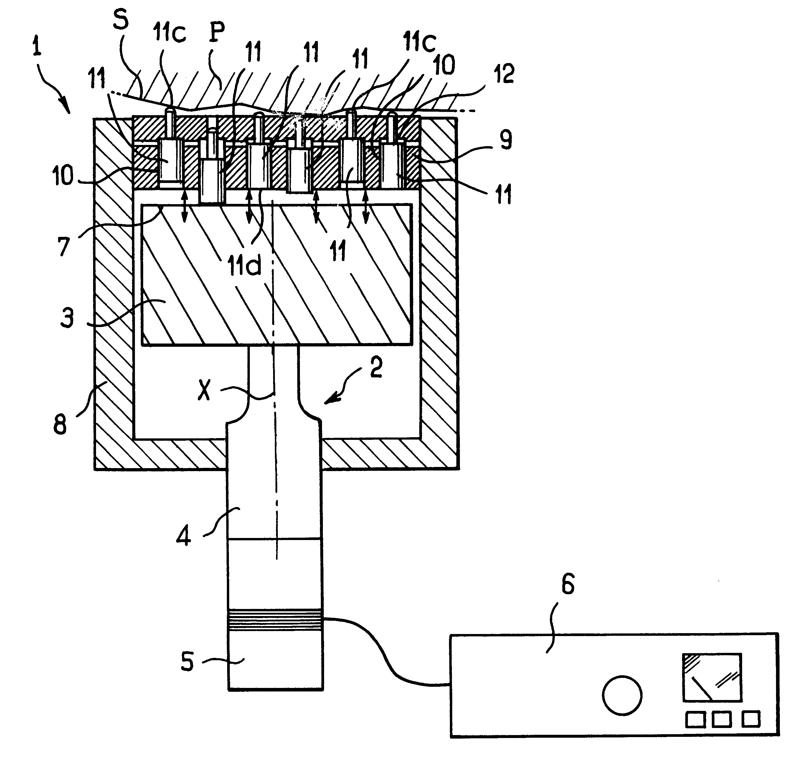
FIG. 2 shows apparatus in accordance with the invention.
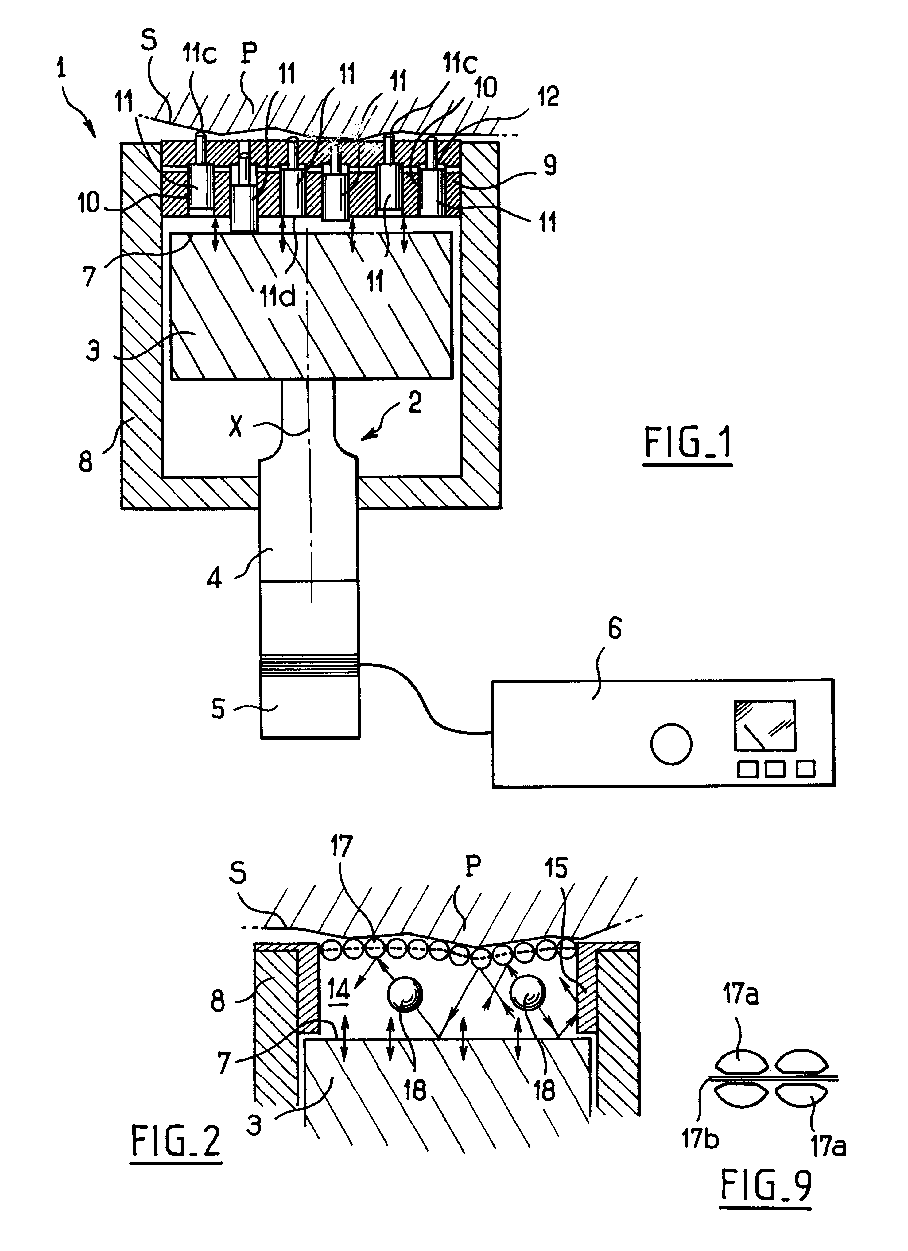
This apparatus differs from the preceding apparatus by the fact that the structure 8 is used in this case to fix a ring 15 whose opening is closed by a carpet of beads 17 serving to retain projectiles 18.
In this case, the projectiles 18 are constituted by balls that are free to move in the space 14 that is defined axially by the carpet of beads 17 and the sonotrode 3, and laterally by the structure 8.
The projectiles 18 are set into motion by the sonotrode 3 vibrating, and they perform multiple rebounds between the vibrating surface 7 and the carpet of beads 17.
The carpet of beads 17 locally transfers the kinetic energy from the projectiles 18 to the surface S of the part P to be treated.
FIG. 9 shows two beads 17a of the carpet of beads 17.
The beads 17a are held by any appropriate fixing means e.g. by means of support wires 17b on which they are mounted with clearance, as shown.
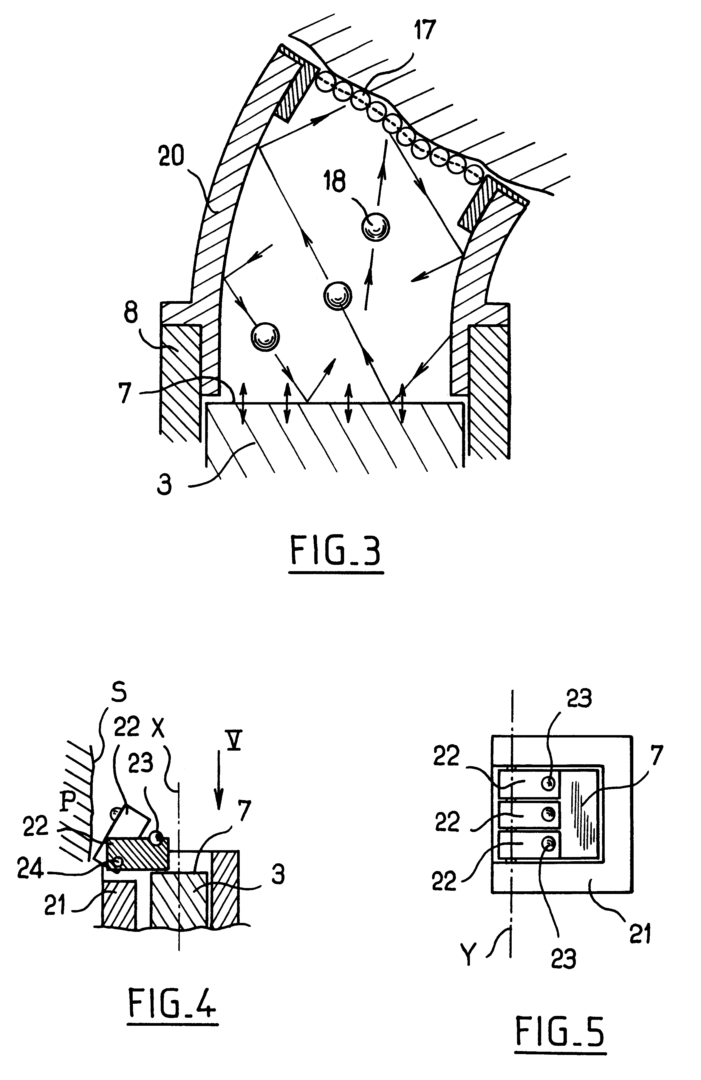
The example of FIG. 3 differs from that of FIG. 2 b...
sixth embodiment
FIGS. 10 and 11 show the invention.
In this embodiment, the projectiles are constituted by balls 40 guided in individual channels 41 formed by tubes 42.
Each ball 40 performs back-and-forth motion in the corresponding tube 42 between the vibrating surface disposed at one end of the tube and the other end which has a pin 43 mounted to move in a guide piece 44 that is dome-shaped, as shown very diagrammatically in FIG. 11.
The axes of the pins 43 extend radially relative to the wall 44.
Each pin 43 comprises a cylindrical body provided with an annular swelling 45 that is about halfway along it, the swelling having axial faces forming frustoconical shoulders 46 and 47.
Each swelling 45 is received in a chamber 49 in the wall 44, which chamber is defined axially by two conical shoulders 50 and 51 against which the shoulders 46 and 47 of the pin 43 can come respectively into abutment.
In a variant (not shown), the shoulders 50 and 51 can be straight, with the shape of the pins 43 being adapted...
PUM
Property
Measurement
Unit
Mass
aaaaa
aaaaa
Mass
aaaaa
aaaaa
Distance
aaaaa
aaaaa
Abstract
The invention relates to apparatus for surface treatment by impact, the apparatus comprising a vibrating surface and at least one projectile suitable for being projected towards the surface to be treated by said vibrating surface. The apparatus includes retaining means for keeping each projectile captive in the apparatus.
Description
The present invention relates to the field of apparatus for surface treatment by impact.It is known that a metal part can be treated by steel shot blasting for the purpose of hardening the part, for example.Shot blasting can be performed under the effect of a jet of compressed air from a shot blaster.The drawback of such a blaster is that it requires a large supply of shot and it is usable only in a space that is adapted to recovering the shot that has rebounded from the part.Apparatuses for surface treatment by impact are also known in which the shot is projected by means of a sonotrode placed in the bottom of a metal bowl whose mouth is positioned in register with and at a small distance from the surface to be treated.Apparatuses of that type present the advantage of the shot returning after rebounding on the part to the sonotrode so as to be projected again against the surface to be treated.There is thus no loss of shot, providing the clearance between the bowl and the part being...
Claims
Application Information
Patent Timeline
Application Date:The date an application was filed.
Publication Date:The date a patent or application was officially published.
First Publication Date:The earliest publication date of a patent with the same application number.
Issue Date:Publication date of the patent grant document.
PCT Entry Date:The Entry date of PCT National Phase.
Estimated Expiry Date:The statutory expiry date of a patent right according to the Patent Law, and it is the longest term of protection that the patent right can achieve without the termination of the patent right due to other reasons(Term extension factor has been taken into account ).
Invalid Date:Actual expiry date is based on effective date or publication date of legal transaction data of invalid patent.

