Flotation plant

a flotation plant and flotation technology, applied in the direction of carburetating air, biological water/sewage treatment, separation process, etc., can solve the problems of reduced flotation plant efficiency, large air bubbles, and ineffective flotation plants

Inactive Publication Date: 2002-02-05
DIPL ING UDO MEYER AQUACONSULT GMBH
View PDF17 Cites 8 Cited by
  • Summary
  • Abstract
  • Description
  • Claims
  • Application Information

AI Technical Summary

Problems solved by technology

Flotation plants in particular operate according to the principle of direct or air flotation, wherein the known direct flotation plants are not very effective since so far only relatively large air bubbles can be produced and delivered to the untreated water.
This in turn results in large air bubbles with the consequence of a reduced efficiency of the flotation plant.
Apart from this, this pressure release flotation has the disadvantage that the air bubble introduction can only be effected from the mixing zone, which also reduces the efficiency of the plant.
However, such fabric mats can yield only relatively large air bubbles, commonly in

Method used


Image

  • Flotation plant
  • Flotation plant
  • Flotation plant

Examples


Embodiment Construction

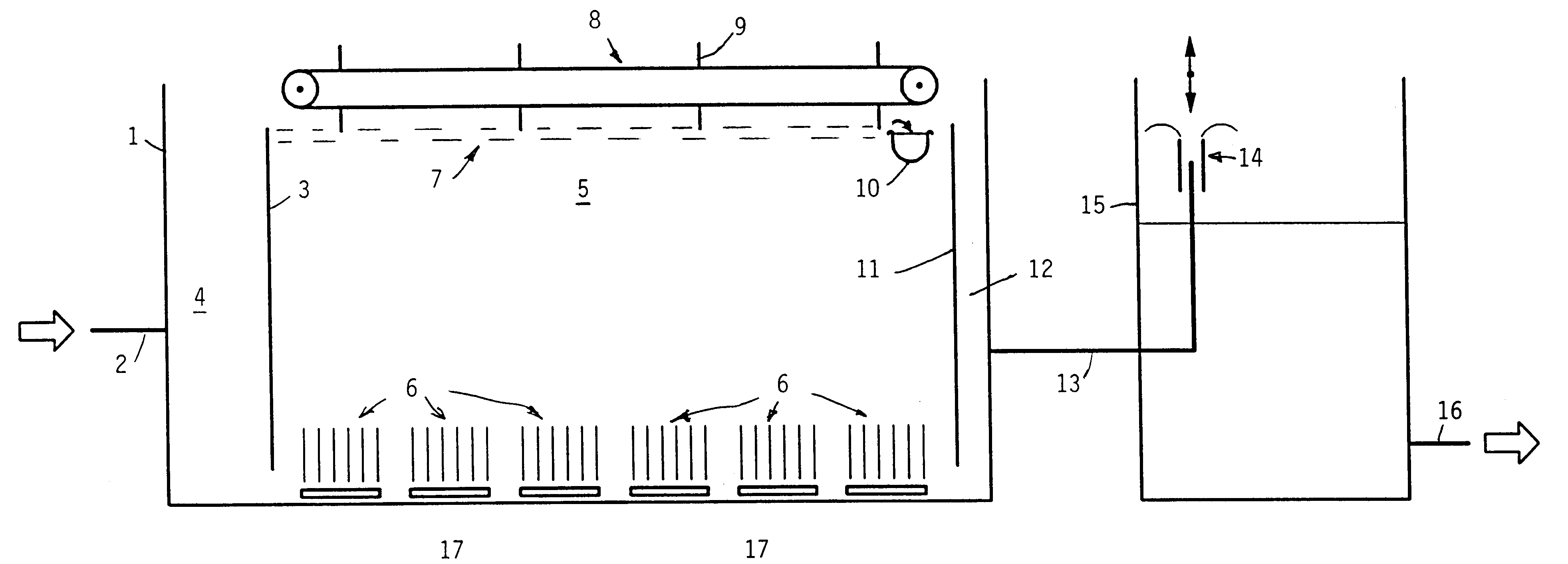
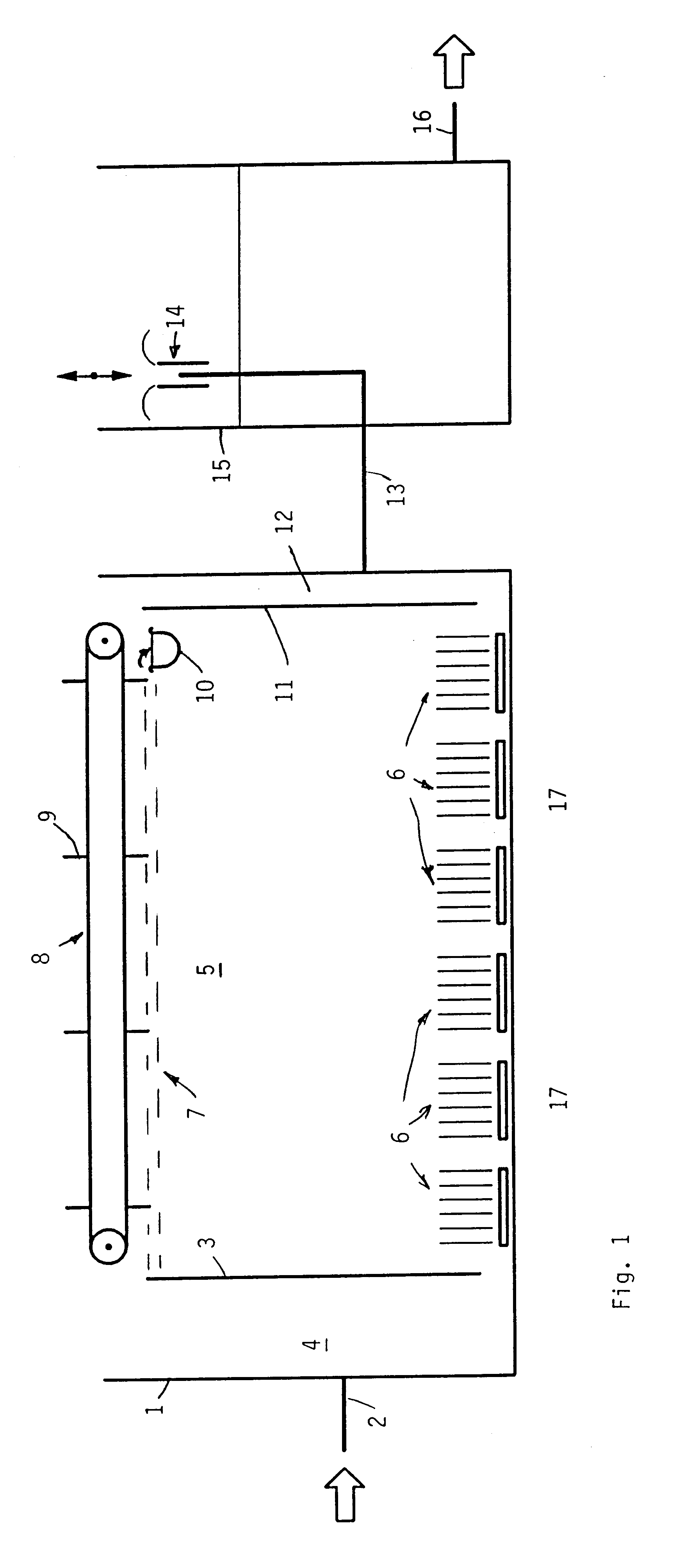
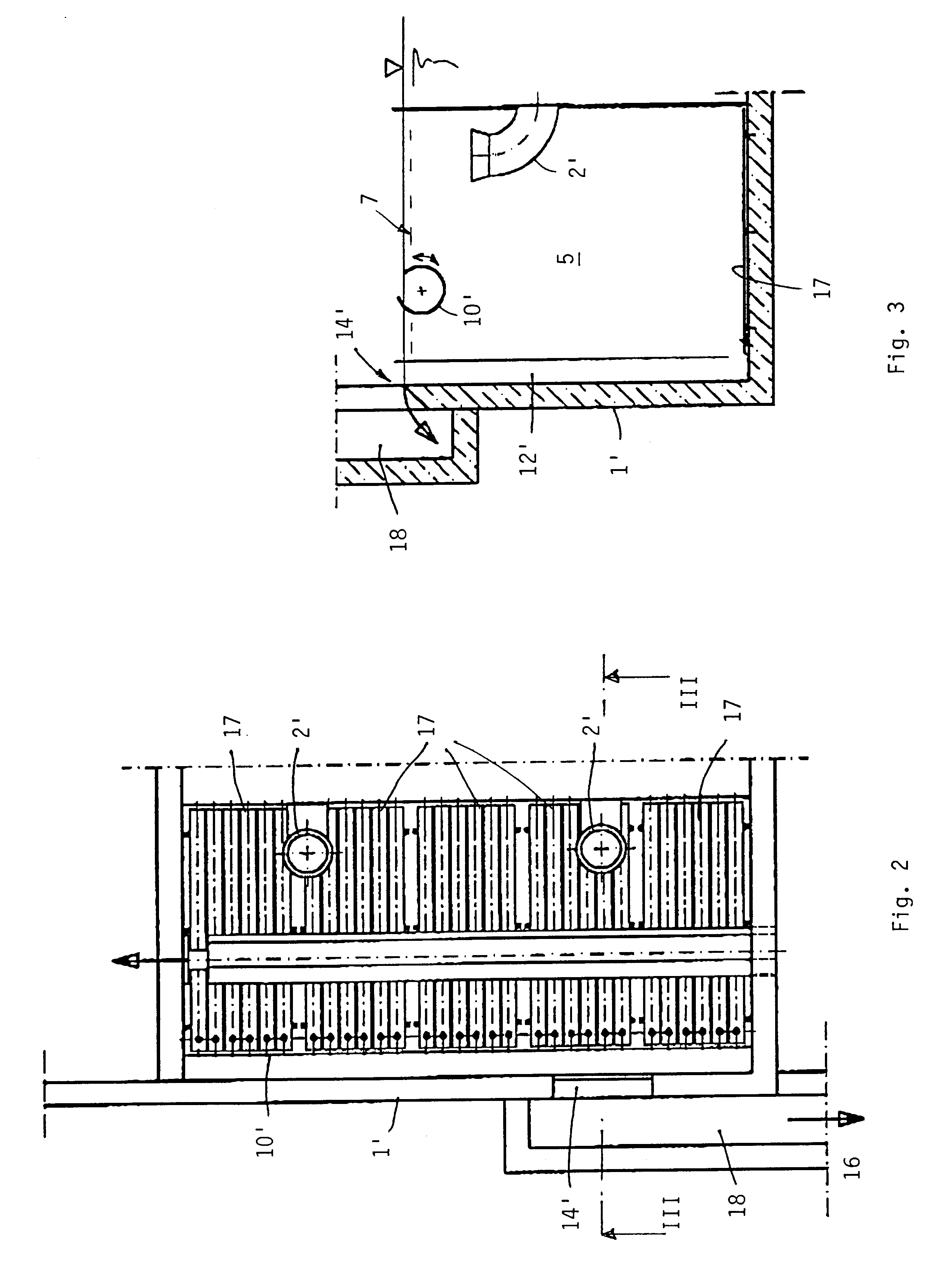
In the flotation plant according to the invention, the air supply means comprise strip- or plate-like membrane aeration devices for installation in the bottom region and including perforated membranes. In this manner, in the present flotation plant, means known per se are used for introducing air bubbles into the untreated water, i.e. Soto-called strip-or plate-aeration means or diffusers wherein a flexible membrane is mounted over a plate under tension, and is provided with a corresponding number of holes to allow the passage of air under formation of bubbles. Such diffusors are already being used in aeration basins, cf. e.g. WO 95 / 35156, yet in aeration basins different specific air loads are present as compared to flotation plants. There, e.g., a specific air load is used which is higher by a factor 100 or more as compared to flotation plants, yet for usual aeration purposes also larger air bubbles are delivered: as a rule, the typical diameter of the air bubbles in these convent...


PUM


Abstract

A flotation plant comprises air supply means with which air bubbles can be supplied to a basin to which untreated water is supplied so as to cause flakes suspended in the untreated water to float by aid of the air bubbles; the air supply means includes strip- or plate-shaped aeration means having perforated membranes and to be installed in the bottom region of said basin.

Description

The invention relates to a flotation plant having an air supply means with which air bubbles can be supplied to untreated water supplied to a basin so as to cause floating of flakes suspended in said untreated water by aid of the air bubbles.BRIEF DESCRIPTION OF BACKGROUND ARTFlotation plants in particular operate according to the principle of direct or air flotation, wherein the known direct flotation plants are not very effective since so far only relatively large air bubbles can be produced and delivered to the untreated water. Therefore, the tendency is to use a so-called pressure release flotation which today is used almost everywhere. To dissolve the air amount required, in pressure release flotation, the air is enriched in water and released at a release valve. In a neighboring mixing zone, the partial flow saturated with air is then mixed with untreated water, whereby air bubbles form. As a rule, this mixing zone is not very large, and frequently coalescing of air bubbles oc...

Claims


Application Information

Patent Timeline
IPC IPC(8): B03D1/14C02F1/24C02F3/20
CPCB03D1/14C02F1/24B03D1/245C02F3/201B03D1/1431Y02W10/10
Inventor MEYER, UDO
Owner DIPL ING UDO MEYER AQUACONSULT GMBH
Why Eureka
Try Eureka