
Component sealing system

a sealing system and component technology, applied in the direction of electrical apparatus construction details, instruments, record information storage, etc., can solve the problems of affecting the proper read/write function of the hda, excessive emi levels, and sometimes necessary rework, so as to fast and secure seal and unseal the hda case elements

Inactive Publication Date: 2002-02-12
SEAGATE TECH HDD HLDG +3
View PDF22 Cites 23 Cited by
  • Summary
  • Abstract
  • Description
  • Claims
  • Application Information

AI Technical Summary

Benefits of technology

The present invention provides a method to quickly and securely seal and unseal HDA case elements, and an apparatus to practice the method. The present invention teaches a conformable, and preferably elastic, sealing band for applying a horizontally biased sealing pressure to the horizontal seam of vertically assembled case elements. An alignment element, disposed on at least one of the sealing band and the assembled case, aligns the band with case seam during assembly, and maintains the band in place once it is assembled to the case. A retaining element may be added to at least one of the case and the sealing band to further secure the band to the case. This retaining element not only aids in positioning the band, but also serves to resist tampering by unauthorized individuals.
The sealing methodology taught herein has the advantage that it can serve to reduce the number of screws or other mechanical fasteners required to conjoin the case elements, as screw clamping pressure is not required to perfect and maintain the seal between case elements. Also, case distortion can be minimized for the same reasons. Further, as no adhesives are used, damage to the case elements is minimized should rework require their separation. The seal leaves no appreciable residue behind on being removed, presents no out-gassing problems, and is easily sealed and unsealed.
The seal taught herein may be impregnated, plated or otherwise coated with electrically conductive material to reduce electromagnetic interference beneath an acceptable threshold level, or to preclude its intrusion into the case entirely. Finally, the methodology taught herein facilitates alignment of the several seal elements during construction, and can be used to minimize unwanted or accidental opening of the sealed case.

Problems solved by technology

EMI can be a significant problem in computer head disc assemblies in that excess levels of EMI can serve to apply an unwanted- signal or noise to interior components of the HDA.
Such noise can interfere with the proper read / write functionality of the HDA.
The case sealing methodology previously outlined presents several problems during the manufacture of HDAs.
A second problem is that during the manufacturing process of HDAs, it is occasionally necessary to rework an HDA being built.
As the number of screws required to mechanically connect the case elements increases, so increases both the amount of time required to assemble and disassemble the drive, as well as the likelihood that the assembly or disassembly process will damage the screw threads of either the screw itself or of the case elements.
Furthermore, it is often the case that a deformable gasket captured and clamped between a first and second case element is permanently deformed thereby or is damaged by the separation of the case elements, necessitating the replacement of the gasket during rework.
Each of these factors adds to the time, expense and effort required to rework an HDA.
While the previously discussed use of pressure sensitive adhesive tape provides an advantage over vertically clamped gaskets, this solution presents a new set of problems to HDA designers.
A first problem is occasioned by the fact that the removal of the tape and / or the adhesive residue therefrom during rework constitutes a further increase in labor costs during rework.
Further, pieces of tape removed during rework may inadvertently be introduced into the case interior, requiring further effort.
A third new problem is occasioned by the fact that adhesives in general, and pressure sensitive adhesives in particular, exhibit an out-gassing of volatile adhesive components, especially the adhesive's solvent or carrier.
These volatile components, when admixed with the ambient atmosphere inside the HDA and dispersed therethrough can adversely effect critical electronic or magnetic components contained inside the HDA.

Method used


Image

  • Component sealing system
  • Component sealing system
  • Component sealing system

Examples


Embodiment Construction

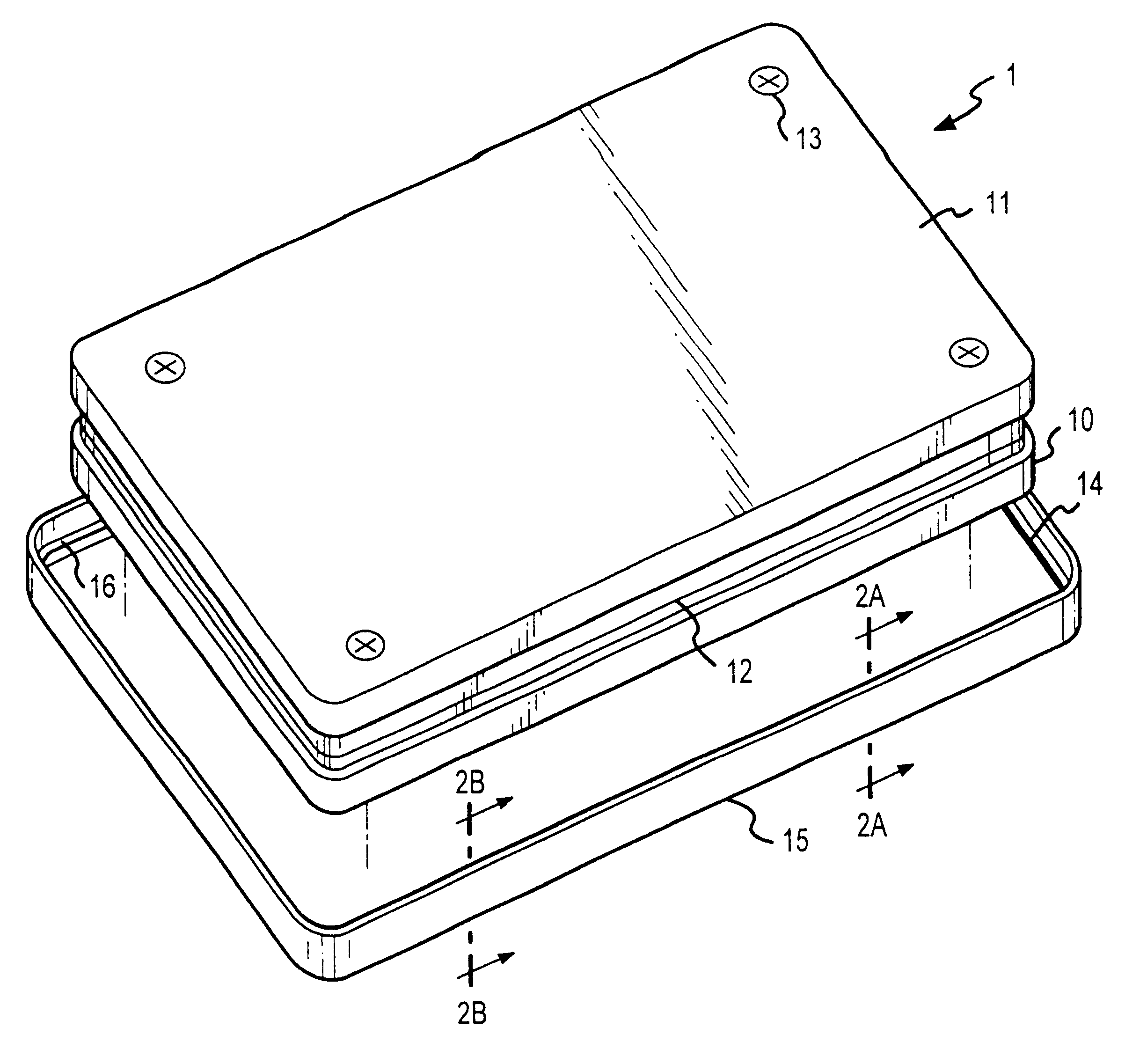
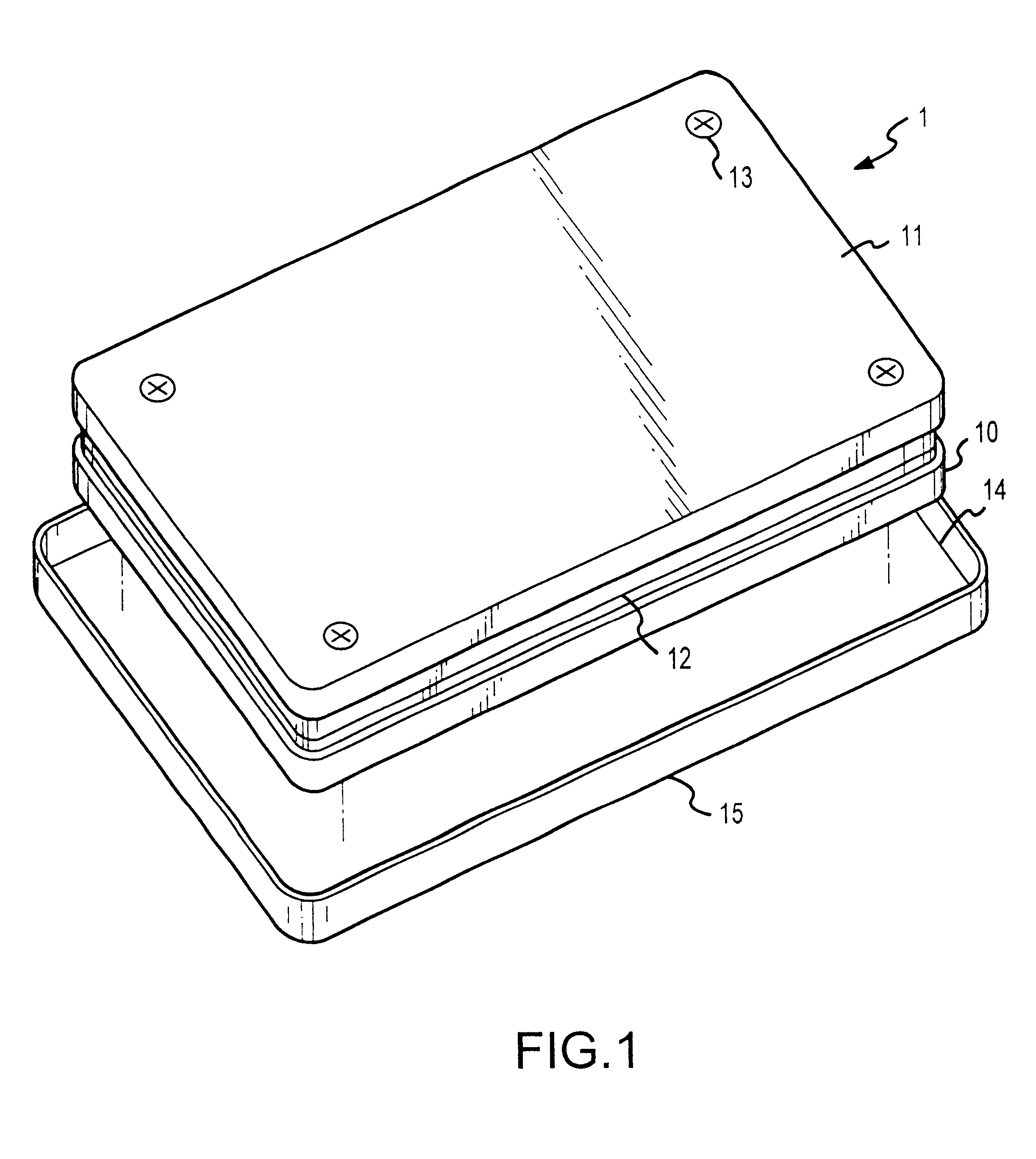
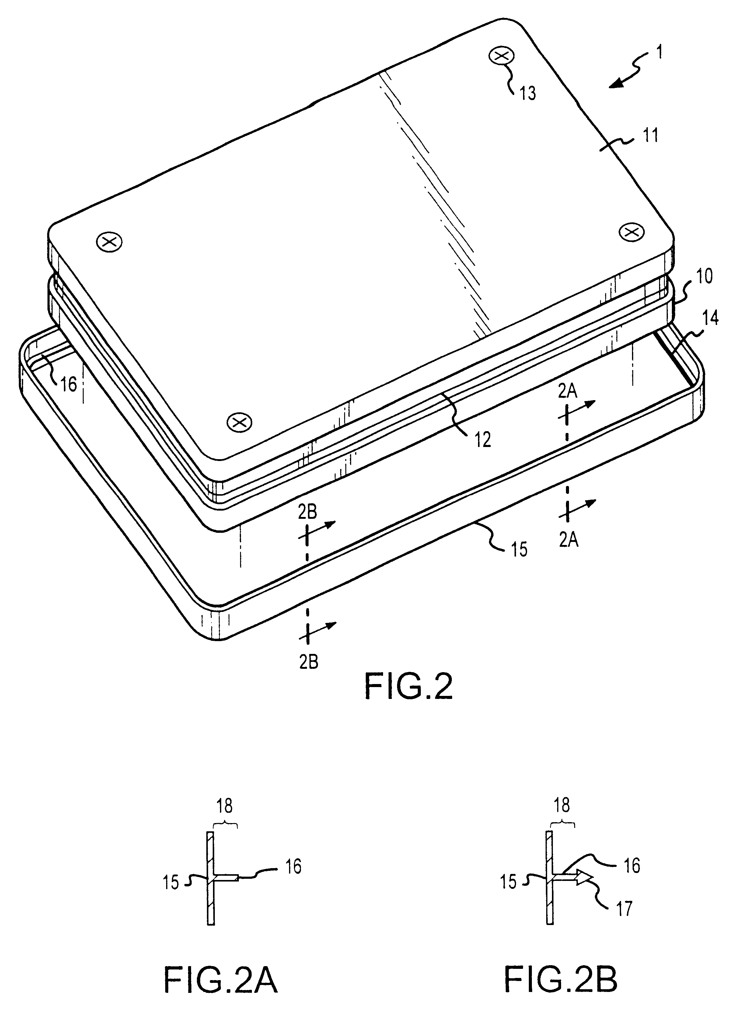
Having reference to FIG. 1, a first preferred embodiment for carrying out the principles of the present invention is shown. Having reference to that figure, case 1 is shown to comprise a pair of horizontally separated case elements, 10 and 11. When assembled together, upper case 11 and lower case 10 define horizontal seam 12 therebetween. Case elements 10 and 11 are held and maintained in mechanical alignment by means of fasteners, for instance machine screws 13.

According to this embodiment upper and lower case elements 11 and 10 respectively, when mechanically fastened and aligned, further define a horizontally annular alignment depression, 14 for receiving therein elastic sealing band 15. Accordingly, it is seen that case 1 comprises a pair of horizontally separated case elements 10 and 11 which are vertically fastened together by machine screws 13.

In order to seal case elements 10 and 11 elastic sealing band 15 is provided. By way of illustration but not limitation, in a first pr...


PUM


Abstract

Method for the removable sealing of a component housing, and apparatus to practice the method using an elastic or conformable sealing band. The present invention teaches a sealing band, preferably elastic, to apply a horizontal seal to the horizontal seam defined by vertically assembled component case elements. The seal is maintained in position over the seam by an alignment element disposed on at least one of the seal and the case. The sealing band is rendered electrically conductive by admixing therewith a conductive material, or by plating thereon a conductive coating. A retaining element may be further added to at least one of the sealing band and the case to minimize tampering with the sealing band once installed.

Description

The present invention relates to a methodology for removably sealing housing elements utilizing an elastic seal element. More particularly, the present invention teaches a removable elastic casing methodology applicable to precision electronic component cases and the apparatus to perform the methodology.In many engineering disciplines, one or more housing or case elements are mechanically conjoined to form a chamber wherein the functional components of a device are housed. It is often the case that one or more of the housing elements is itself a functional component of a device. One such example is the housing elements of a computer head disc assembly (HDA). Typically, in most current production HDAs, at least one of the case elements also serves as a mounting frame for mounting at least some of the HDA functional components thereto.It is often desirable that the housing elements, when mechanically conjoined, provide not only a stable mechanical, electrical, hydraulic, pneumatic or ...

Claims


Application Information

Patent Timeline
Patent Type & Authority Patents(United States)
IPC IPC(8): G11B33/14G11B33/12
CPCG11B33/121G11B33/1466Y10T29/4987
Inventor KAZMIERCZAK, FREDERICK FRANKRAFFETTO, MICHAEL JOHNANDREWS, MICHAEL KENNETHMAIERS, MICHAEL ALAN
Owner SEAGATE TECH HDD HLDG
Learn More