

Internal antenna for an apparatus
an antenna and apparatus technology, applied in the direction of antennas, antenna supports/mountings, radiating element structural forms, etc., can solve the problems of reducing the antenna, reducing the electrical characteristics of the antenna, and reducing the efficiency of the antenna
Inactive Publication Date: 2002-02-19
PULSE FINLAND
View PDF11 Cites 97 Cited by
- Summary
- Abstract
- Description
- Claims
- Application Information
AI Technical Summary
Benefits of technology
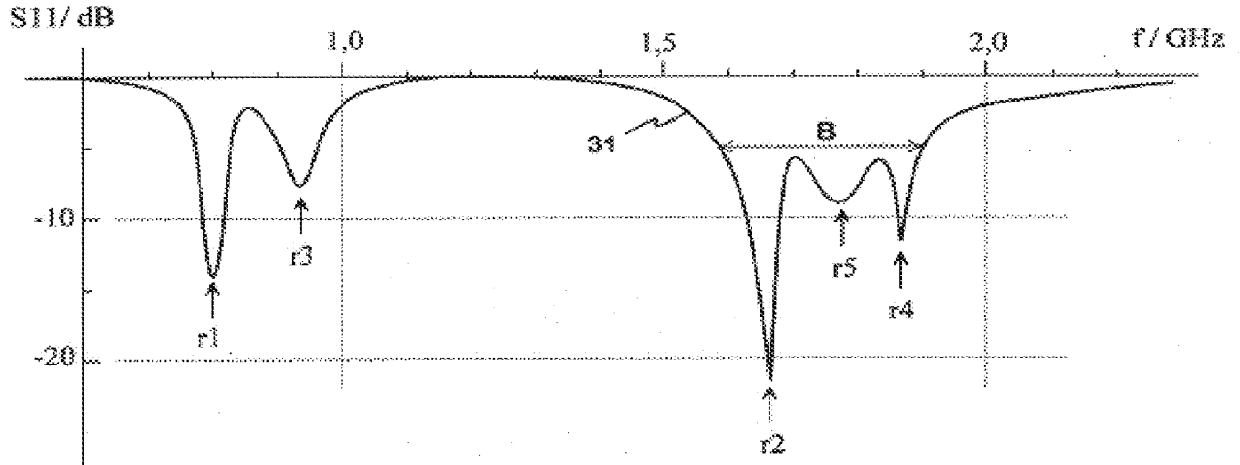
An advantage of the invention is that it achieves a greater increase in the antenna bandwidth than what would be achieved by placing the only radiating plane at a distance from the ground plane equal to that of the upper radiating plane according to the invention. This is due to the use of multiple resonance frequencies close to each other. Other advantages of the invention include relatively good manufacturability and low manufacturing costs.
Problems solved by technology
Likewise, reducing the antenna in the directions of breadth and length by making the physical lengths of the elements smaller than their electrical lengths especially degrades the efficiency.
The disadvantage of structures like the one described in FIG. 1 is that the tendency towards smaller antennas for compact mobile stations will in accordance with the foregoing degrade the electrical characteristics of an antenna too much.
Method used
View moreImage
Smart ImageViewing Examples

Examples
second embodiment
FIG. 4a and 4b show the invention,
third embodiment
FIG. 5a and 5b show the invention,
fourth embodiment
FIG. 6a and 6b show the invention, and
FIG. 7 shows an example of a mobile station equipped with an antenna according to the invention.
Login to View More PUM
 Abstract
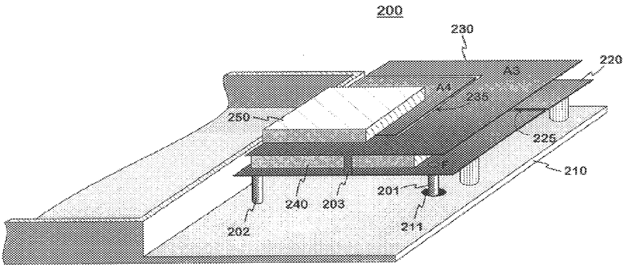
The invention relates to an antenna structure to be installed inside small-sized radio apparatus. A conventional PIFA-type structure is extended such that on top of the ground plane (210) there will be instead of one at least two radiating planes (220, 230) on top of each other. There is between them dielectric material (240) to reduce the size of the lower radiator and to improve the band characteristics. Likewise, there is dielectric material (250) on top of the uppermost radiating plane so as to bring one resonance frequency of the antenna relatively close to another resonance frequency in order to widen the band. Advantageously the radiating planes are in galvanic contact (203) with each other. The invention accomplishes a greater increase in the antenna bandwidth as compared to that achieved by placing the only radiating plane at a distance from the ground plane equal to that of the upper radiating plane according to the invention.
Description
This application claims priority from Finnish Patent Application No. 19992268, entitled "Internal Antenna for an Apparatus," filed on Oct. 20, 1999, the disclosure of which is hereby incorporated by reference in its entirety.1. Field of the InventionThe invention relates to an antenna structure to be installed inside sm radio apparatus.2. Description of Related ArtIn portable radio apparatus it is very desirable that the antenna be located inside the covers of the apparatus, for a protruding antenna is impractical. In modem mobile stations, for example, the internal antenna naturally has to be small in size. This requirement is further emphasized as mobile stations become smaller and smaller. Furthermore, in dual-band antennas the upper operating band at least should be relatively wide, especially if the apparatus in question is meant to function in more than one system utilizing the 1.7-2 GHz band.When aiming at a small-sized antenna the most common solution is to use a PIFA (plana...
Claims
Login to View More Application Information
Patent Timeline
 Patent Type & AuthorityPatents(United States)
IPC IPC(8): H01Q1/40H01Q5/00H01Q9/04H01Q1/00
CPCH01Q1/40H01Q9/0414H01Q5/378H01Q5/371H01Q9/0421
InventorANNAMAA, PETTERIMIKKOLA, JYRKI
OwnerPULSE FINLAND