Electron equipment

a technology of electric equipment and comb gear, which is applied in the field of electric equipment, can solve the problems of insufficient durability, inability to machine the comb gear portion of the vibrator, and inability to wear the contact portion of the rotor and the comb gear,

Inactive Publication Date: 2002-02-19
CITIZEN WATCH CO LTD
View PDF4 Cites 33 Cited by
  • Summary
  • Abstract
  • Description
  • Claims
  • Application Information

AI Technical Summary

Problems solved by technology

Vibration caused by the rotation of the eccentric weight wheel is transmitted to the user's arm through the watch case, thereby alarming the user by a vibration alarm.
Then, wear of the contact portion of the rotor and the comb gear portion is unavoidable, providing ...

Method used


Image

  • Electron equipment
  • Electron equipment
  • Electron equipment

Examples


Embodiment Construction

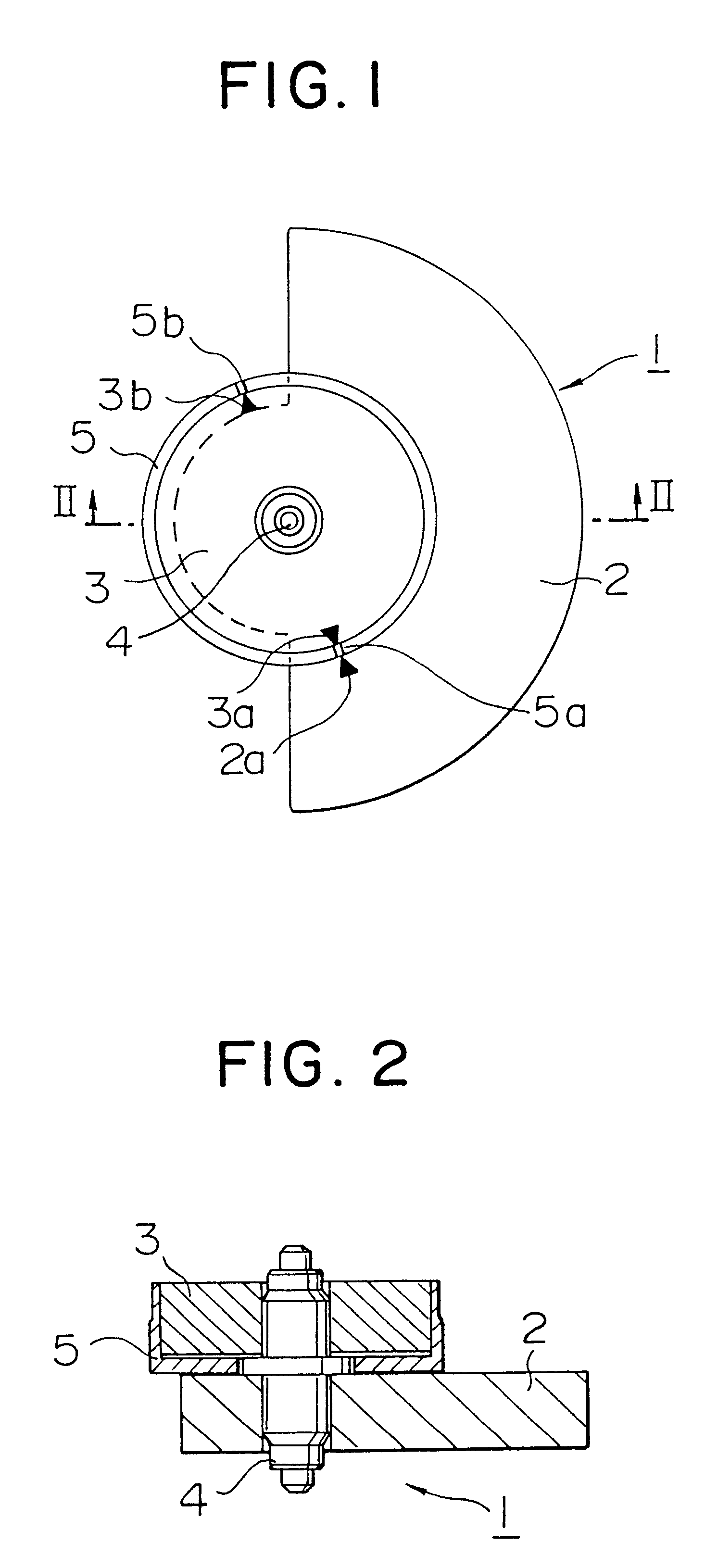
Several preferred embodiments of the present invention will be described with reference to the accompanying drawings. FIG. 1 is a plan view of a rotor driven by a flat stator type bipolar stepping motor of an electronic equipment with a vibration alarm according to the present invention, and FIG. 2 is a sectional view taken along the line II--II of FIG. 1.

Reference numeral 3 denotes a rotor magnet; 4, a rotor shaft; 5, a rotor magnet frame; and 2, an eccentric weight having the barycenter at a position deflected from the rotor shaft 4 as its rotary shaft. The eccentric weight 2, the rotor magnet 3, the rotor shaft 4, and the rotor magnet frame 5 constitute a rotor 1. Reference numeral 2a denotes a printed mark provided to the eccentric weight 2; 3a, a printed mark provided to the rotor magnet 3; and 5a, a notched mark provided to the rotor magnet frame 5.

The assembly procedure of the rotor 1 will be described as follows. The eccentric weight 2 is directly fixed to the rotor shaft 4....


PUM


Abstract

A small electronic equipment with a vibration alarm has, as a drive source, a flat stator type bipolar stepping motor, which has a rotor having high durability, can be assembled easily, requires low power consumption, is started constantly stably, and can be rotated at a high speed. In this electronic equipment with the vibration alarm, a rotor (1) is rotated by a rotary drive system including a drive pulse generating means (112, 113, 114), a drive circuit (110), a flat stator (6), a counter electromotive voltage detection coil (306), and a magnetic pole position detection means (107, 115, 116), so that an eccentric weight (2) fixed to the rotor is rotated, thereby generating vibration. The drive pulse generating means outputs a pulse signal for driving the stepping motor on the basis of an alarm signal output at alarm time. The drive circuit supplies a drive current to a drive coil (305) on the basis of the pulse signal from the drive pulse generating means. The flat stator transmits the magnetomotive force generated in the drive coil to the rotor (1). The counter electromotive voltage detection coil detects a counter electromotive voltage generated by rotation of the rotor. The magnetic pole position detection means detects the magnetic pole position of the rotor (1), which is rotating, with respect to the flat stator (6) on the basis of the counter electromotive voltage generated in the counter electromotive voltage detection coil, and outputs, to the drive pulse generating means, a detection signal for controlling the output timing of the pulse signal supplied from the drive pulse generating means (114).

Description

The present invention relates to an electronic equipment with a vibration alarm and, more particularly, to a stepping motor incorporated in an electronic equipment with a vibration alarm for alarming the user by transmitting vibration to the user's arm.BACKGROUND ART OF THE INVENTIONAs disclosed in Japanese Utility Model Laid-Open Nos. 2-6291 and 2-107089, a conventional wristwatch with a vibration alarm as an electronic equipment for generating vibration by rotating an eccentric weight by a motor incorporates an ultrasonic motor. The rotation of the rotor of the ultrasonic motor is transmitted to an eccentric weight wheel having an eccentric barycentric position. Vibration caused by the rotation of the eccentric weight wheel is transmitted to the user's arm through the watch case, thereby alarming the user by a vibration alarm.In the ultrasonic motor of the Japanese Utility Model Laid-Open Nos. 2-6291 and 2-107089, a vibrator bonded with a piezoelectric element is supported by a su...

Claims


Application Information

Patent Timeline
IPC IPC(8): G04G13/02G04B25/00G04B25/04G04G13/00
CPCG04G13/021G04B25/04
Inventor MIYAUCHI, NORIONITTA, TATSUOMURAKAMI, TOMOMI
Owner CITIZEN WATCH CO LTD
Why Eureka
Try Eureka