Ink jet printing device and circuit

Inactive Publication Date: 2002-03-05
IMAJE
View PDF10 Cites 43 Cited by
  • Summary
  • Abstract
  • Description
  • Claims
  • Application Information

AI Technical Summary

Problems solved by technology

It does not permit an ink jet droplet speed regulation.
This non-reversible pump does not make it possible to implement rapidly all the cycles necessar

Method used


Image

  • Ink jet printing device and circuit
  • Ink jet printing device and circuit
  • Ink jet printing device and circuit

Examples


Embodiment Construction

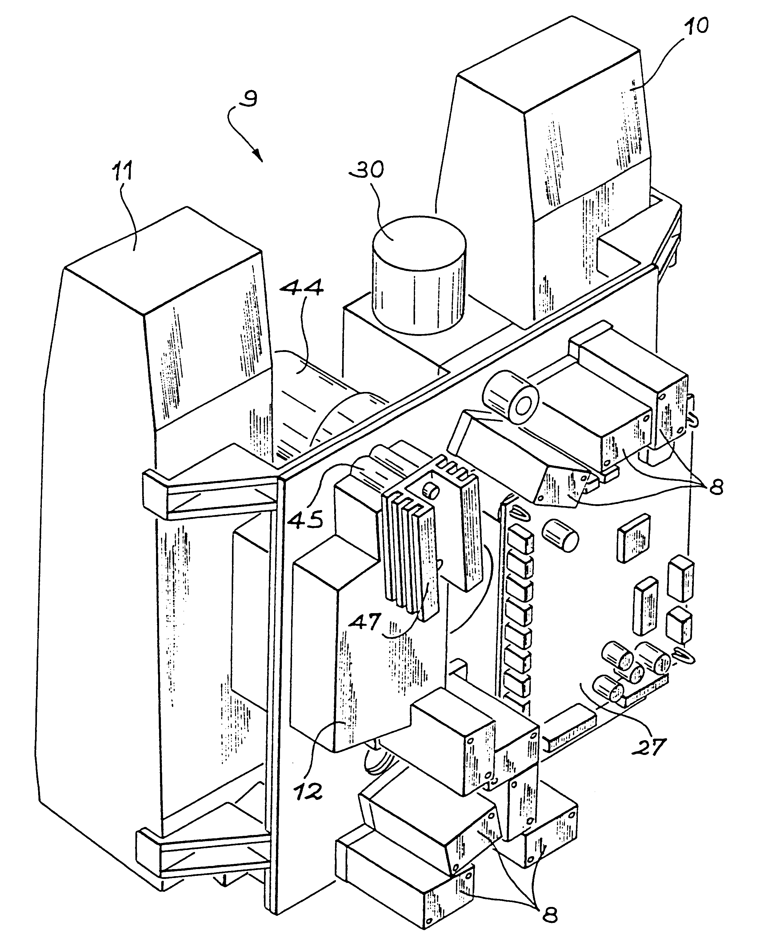
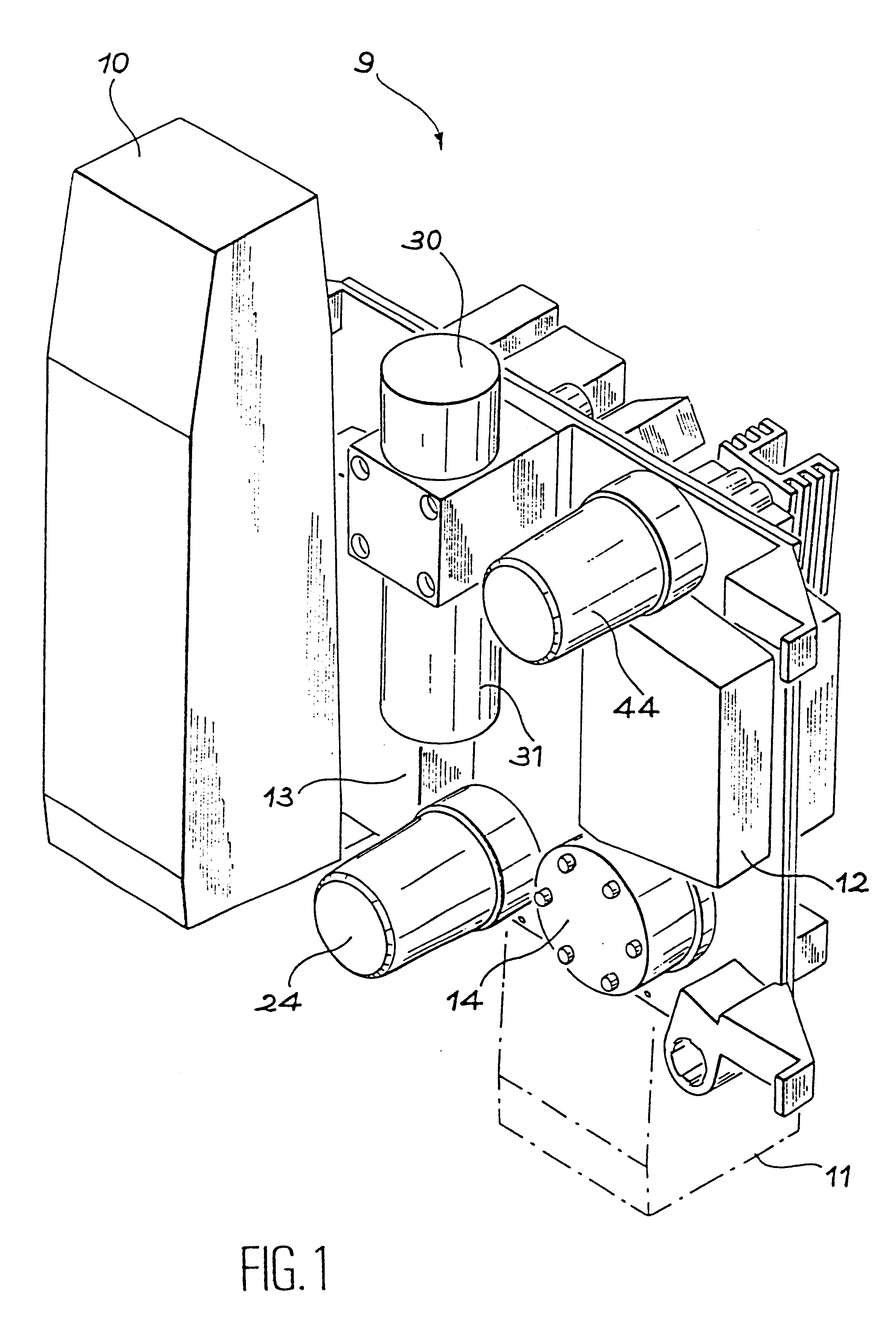
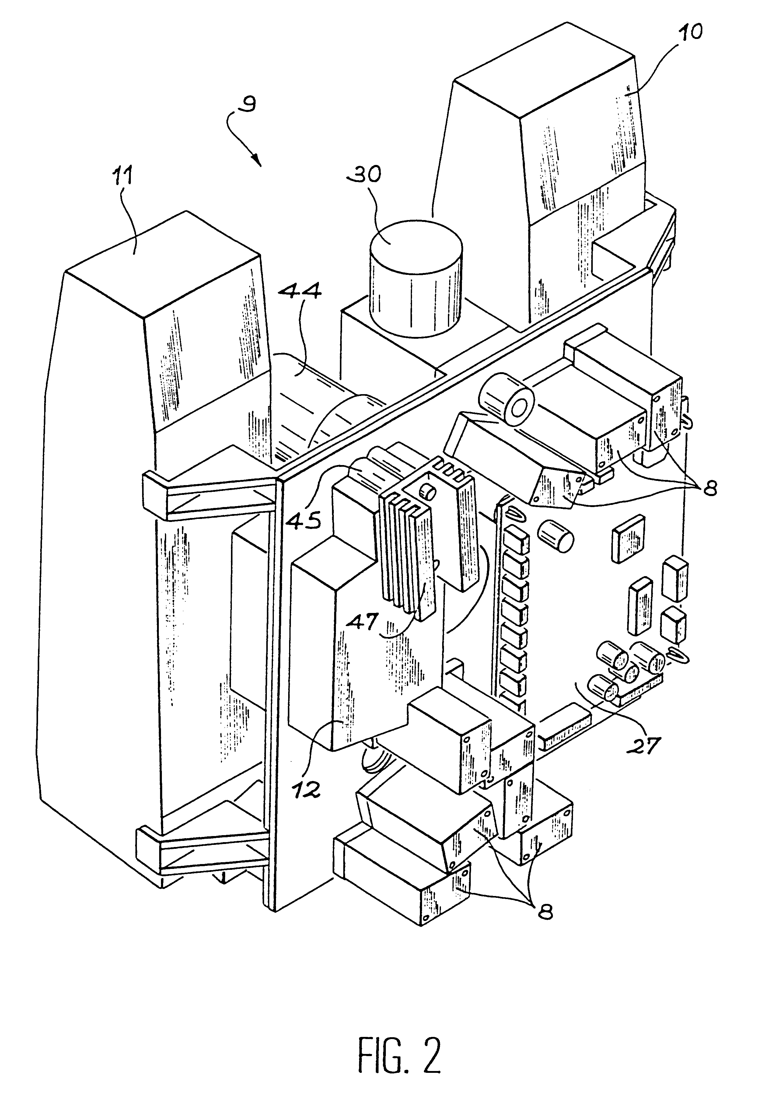
The present invention describes an ink circuit more particularly comprising an ink cartridge, an additive cartridge, a recovery tank, an accumulator or storage tank, a main filter, solenoid valves, an ink transfer pump equipped with a pressure and temperature sensor, which provides information on the operational hydraulic and thermal conditions and an air pressure regulator, said ink circuit being characterized in that it comprises a double face support unit having a hydropneumatic face and an electronic face making it possible to separate the hydraulic, pneumatic and electronic assemblies, all the functional components being fitted outside one or other of the two faces.

Advantageously, the relative arrangement of certain components contributes to an improvement in the overall functionality of the ink circuit. Thus, the air / ink separation is ensured by an arrangement of the air-operating components in the upper part of the circuit and the mainly ink-operating components in the lower ...


PUM


Abstract

The present invention relates to an ink circuit comprising an ink cartridge (10), an additive cartridge (11), a recovery tank (12), a storage tank or accumulator 913), a main filter (24), solenoid valves (8), an ink transfer pump (14) equipped with a pressure/temperature sensor (53), an air pressure regulator (30), said ink circuit comprising a double face support unit with a hydropneumatic face and an electronic face making it possible to separate the hydraulic, pneumatic and electronic assemblies, all the functional components being fitted outside on one or other of the two faces.

Description

DESCRIPTION1. Technical FieldThe present invention relates to an ink circuit, as well as to an ink jet machine and a conditioning machine or a conveyor using such a circuit.2. Prior ArtA prior art device is described in U.S. Pat. No. 4,862,192. This device is an ink jet point printer, with an ink circuit incorporating a device for the transfer of thick ink from a first supply tank and, independently thereof, additives from a second supply tank, into an ink chamber. Ink from said ink chamber is supplied under pressure to a writing head. Ink is returned to the ink chamber through a recovery channel, traversing the writing head and recovering the ink droplets which have not been deflected for writing purposes. The transfer device uses pressurized air for transporting the ink between an ink tank connected to the writing head, a mixture tank connected to the supply tanks, and a recovery tank connected to the recovery channel. The mixture or mixing tank can be alternatively connected to a...

Claims


Application Information

Patent Timeline
IPC IPC(8): B41J2/175
CPCB41J2/17523B41J2/175
Inventor PAGNON, ALAINSOUVIGNET, ANDRE
Owner IMAJE
Why Eureka
Try Eureka