Chemical filter unit and gas purification system

Inactive Publication Date: 2002-03-05
TORAY IND INC
View PDF25 Cites 47 Cited by
  • Summary
  • Abstract
  • Description
  • Claims
  • Application Information

AI Technical Summary

Problems solved by technology

With the improvement of production techniques in the respective industries, the demand for cleanness becomes very severe.
However, it has been found that when the air in a closed clean space is used cyclically through filters, some of the misty or gaseous chemical substances contained in the air are rather concentrated to levels higher than those in open air.
The reason is that in the conventional cleaning of air, the necessity of removing misty or gaseous chemical substances contained in the air has not been noticed, and therefore that the conventional air cleaners did not have such a function.
Ammonia causes haze and dielectric breakdown in the product, and its presence greatly lowers the yield of the product.
This causes a very serious problem called T-TOP failure.
However, this technique does not state any possibility of removing ammonia by adsorption down to a very low concentration (order of ppb), or any method for lessening the pressure loss of the filter using the filter medium, or any method for increasing the substance adsorption capacity per unit

Method used


Image

  • Chemical filter unit and gas purification system
  • Chemical filter unit and gas purification system
  • Chemical filter unit and gas purification system

Examples


Example

COMPARATIVE EXAMPLE 1

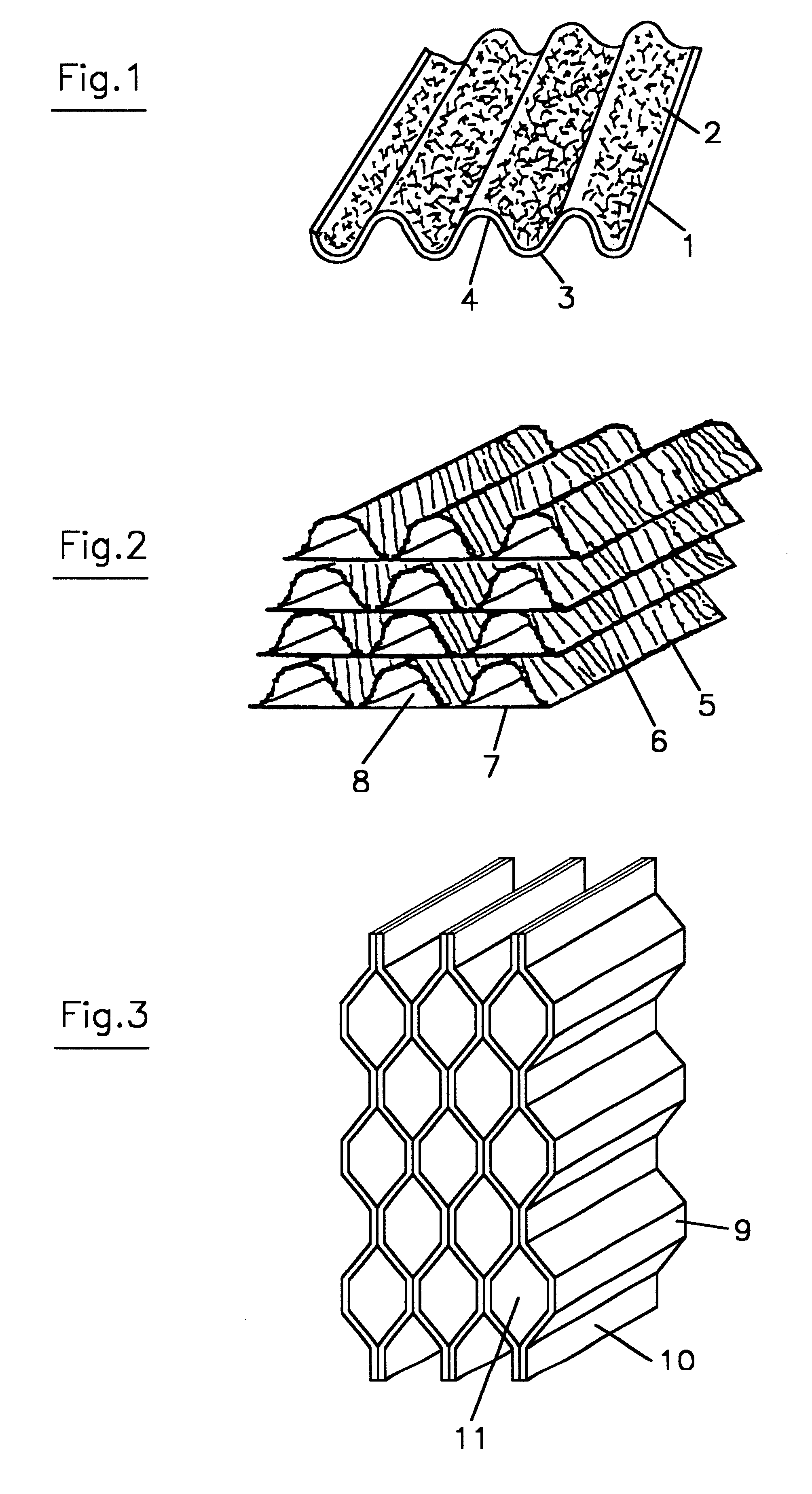
The fiber sheets prepared as described for the Example were corrugated as described for the Example, except that the void after corrugation was changed. From the obtained corrugated board, the same corrugated sheets as obtained in the Example were cut out, and from them, a filter unit was produced as described for the Example. The total weight of the filter medium in the filter unit was 4870 g. The ion exchange capacity per unit volume was 290 eq / m.sup.3.

The filter unit was used to perform the same ammonia absorbability test as in the Example. The pressure loss of the filter medium of the filter unit was 1.3 mm Aq, being lower than that obtained in the Example.

Though a high ammonia removal rate was observed in the beginning of the test, it was found that the removal rate declined at a high rate with the progression of test. As a result of simulation, the life of the filter unit was judged to be 590 days. According to the equipment repair practice in the industry...

Example

COMPARATIVE EXAMPLE 2

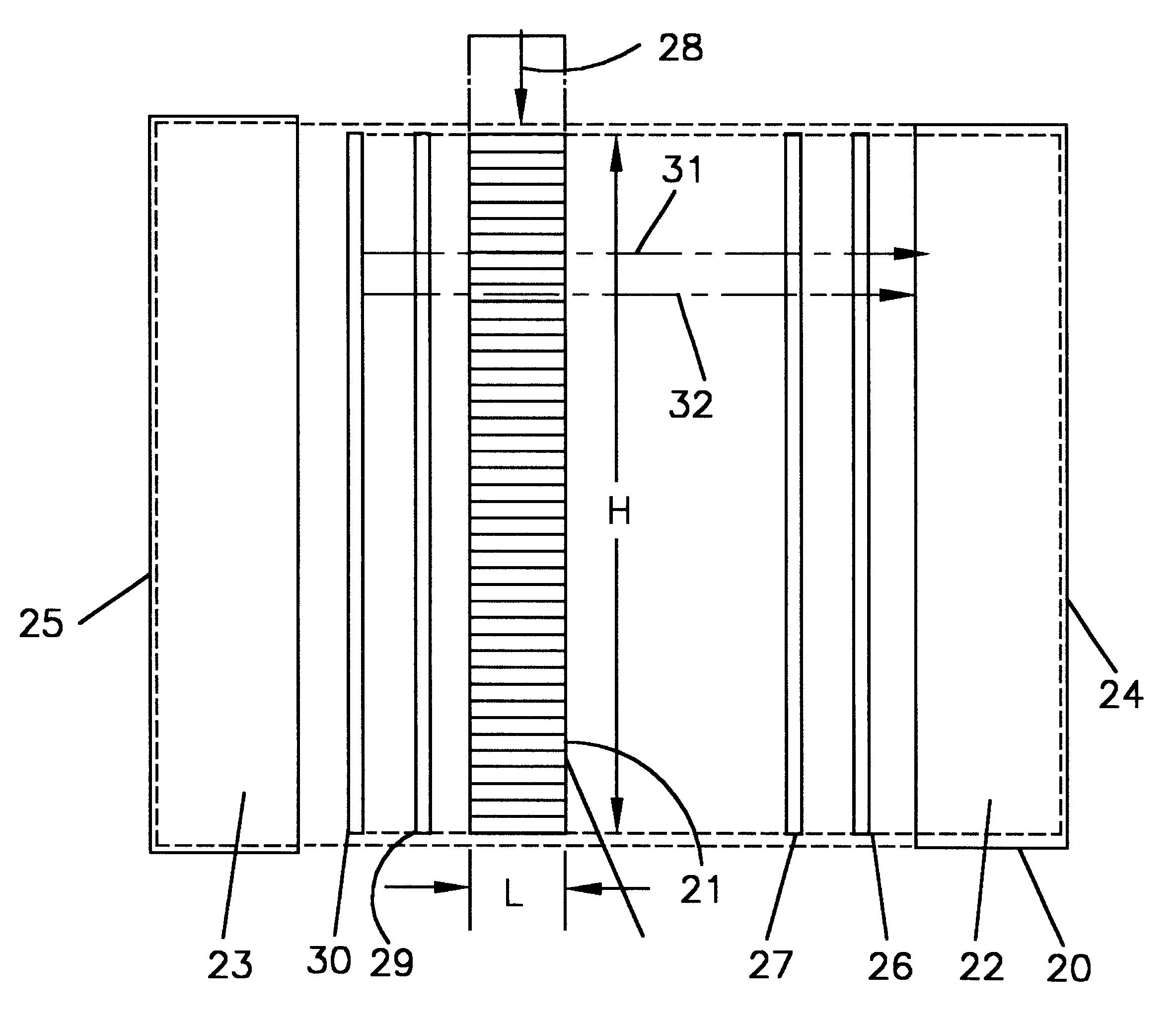
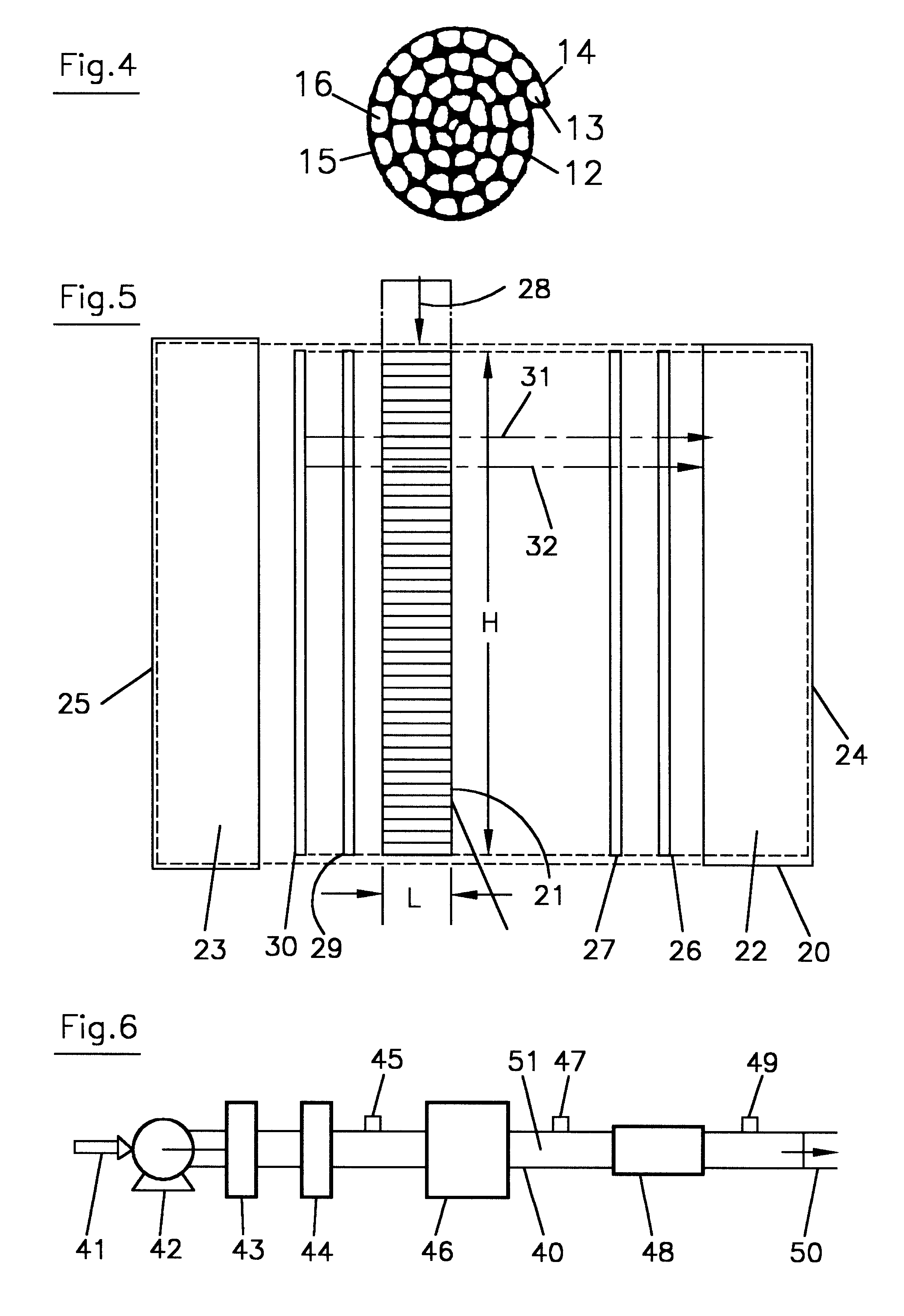
For a marketed filter unit (the width of 590 mm.times. the height of 590 mm (H).times. the depth of 70 mm (L) filter medium) in which an ion exchange non-woven fabric obtained by irradiating a polyolefin filament non-woven fabric with electron rays to form graft sites and converting the fibers into cation exchange fibers by graft reaction is installed in a housing together with spacers formed by aluminum wires, the same test as performed for the Example was performed.

The ion exchange capacity of the filter medium was 2.5 meq / g, and the weight of the installed filter medium was 2068 g. The ion exchange capacity per unit volume of the filter medium was 220 eq / m.sup.3.

As a result of simulation, the life of the marketed filter unit was judged to be 586 days, but the pressure loss of the filter medium was as very high as 6.0 mm Aq.

Since the gas flow velocity had to be kept at the same level as that in the Example, the fan from the Example had to be changed to a fan w...


PUM

PropertyMeasurementUnit
Lengthaaaaaaaaaa
Depthaaaaaaaaaa
Depthaaaaaaaaaa

Abstract

A chemical filter unit, which comprises a filter medium formed by laminating a plurality of fiber sheets an a housing the filter medium, and has a gas inlet open on one face of the housing and a gas outlet open on the other face substantially in opposite to the gas inlet, characterized in that gas passages to allow the flow of the gas along the surfaces of the fiber sheets are formed between the respectively adjacent fiber sheets of the filter medium from the gas outlet to the gas outlet, and that the adsorption capacity of the filter medium is 300 eq/m3 or more. It is preferable that the fibers constituting the fiber sheets are ion exchange fibers.

Description

The present invention relates to a chemical filter unit and a gas cleaning system.The present invention relates to a chemical filter unit and a gas cleaning system which can decrease the chemical pollutants in a gas, particularly in the air supplied to a clean room, clean booth or clean bench, etc. (hereinafter called a closed clean space) to very low levels by using ion exchange or electric charge adsorbing action, are low in the pressure loss of the gas to be treated and can be used for a long period.BACKGROUND ARTSIn recent years, in the electric and electronic industry, biochemical industry, etc., the demand for closed clean spaces has been sharply increasing. With the improvement of production techniques in the respective industries, the demand for cleanness becomes very severe. In this connection, techniques for analyzing pollutants are also improving dramatically in these years. As a result, the necessity of removing conventionally overlooked substances has been noticed.The c...

Claims


Application Information

Patent Timeline
IPC IPC(8): B01D39/16B01D53/04
CPCB01D39/1607B01D53/0415B01D53/025B01D53/0446B01D2259/4508B01D2253/202B01D2253/304B01D2253/3425B01D2257/406B01D2253/102B01D39/16
Inventor HIRATA, NAMIFUJUMURA, YOICHISARUYAMA, HIDEOAMANO, MASAKI
Owner TORAY IND INC
Why Eureka
Try Eureka