Coaxial connector

a technology of coaxial connectors and connectors, applied in the direction of coupling device details, coupling device connections, aperture leaage reduction, etc., can solve the problems of complex operation, low shielding effect, and high price of bracelets, and achieve good shielding

Inactive Publication Date: 2002-03-12
RADIALL SA
View PDF7 Cites 32 Cited by
  • Summary
  • Abstract
  • Description
  • Claims
  • Application Information

AI Technical Summary

Benefits of technology

The present invention makes it possible simultaneously to obtain good shielding and fixing between the connector and the metal box that is relatively flexible.
The grounding plate can be mounted on the panel and it can be dismounted therefrom in particularly simple manner.
This makes it possible to implement the opening with relatively large positioning tolerance.

Problems solved by technology

Nevertheless, they prevent the connector moving when fixed to the metal box and they give rise to complex operations for mounting the connector on the box and for dismounting it therefrom.
Nevertheless, such bracelets are expensive and provide little freedom of displacement for the connector relative to the box.

Method used


Image

  • Coaxial connector
  • Coaxial connector
  • Coaxial connector

Examples


Embodiment Construction

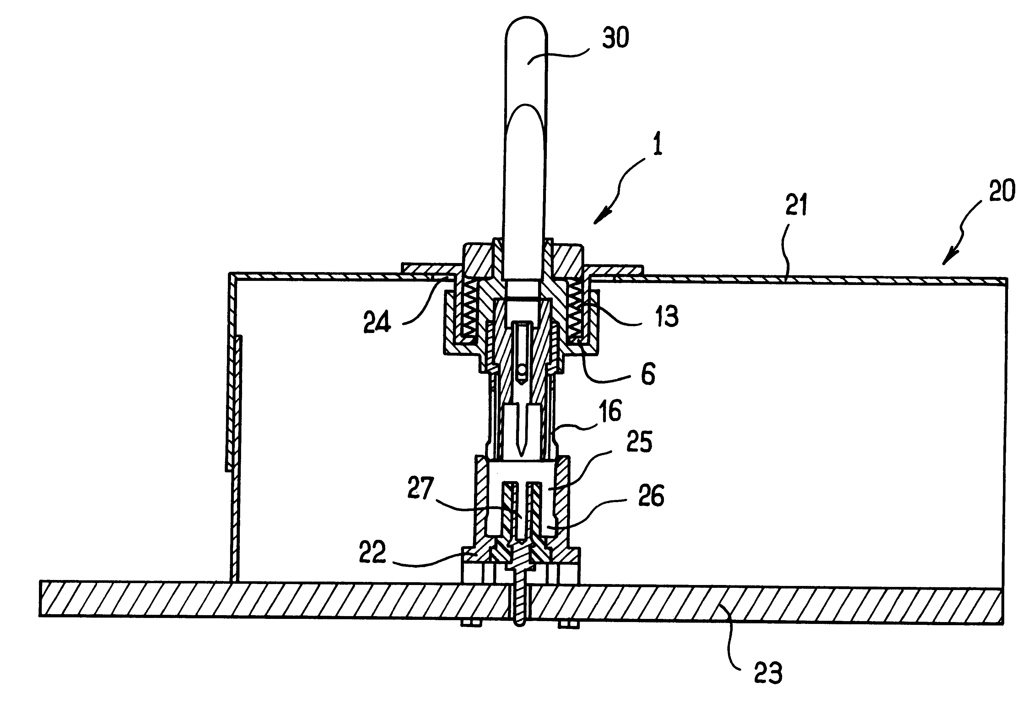
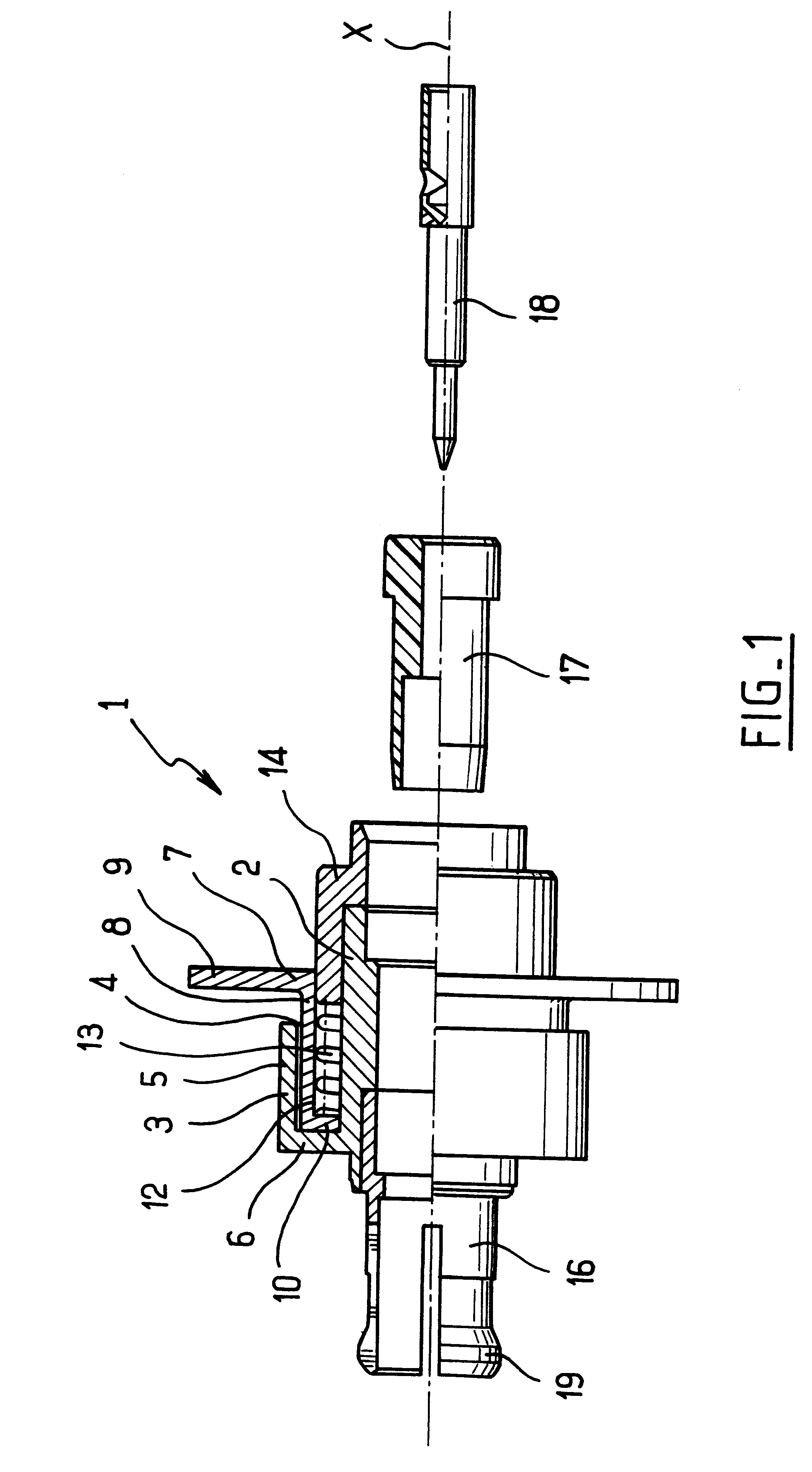
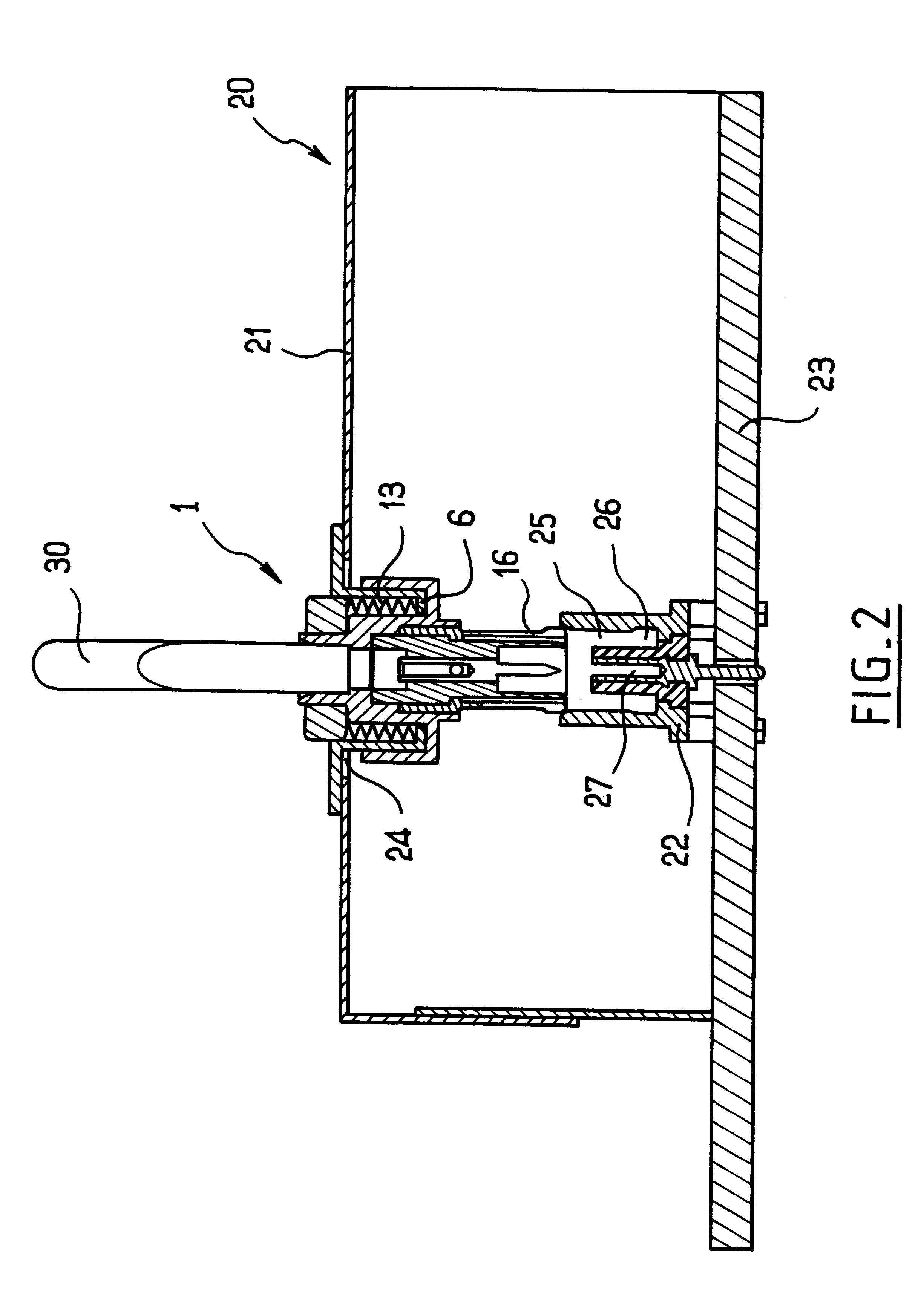
FIG. 1 shows a coaxial connector 1 comprising a body 2 that is circularly tubular about the axis X.

The body 2 has an extension 3 from its side wall that constitutes a housing 4.

The extension 3 has a tubular wall 5 that is circularly symmetrical about the axis X and parallel with the outside of the tubular wall of the body 2.

The wall 5 and the tubular wall of the body 2 are connected together by a radial wall 6 defining the end wall of the housing 4.

In the embodiment shown in FIG. 1, the axial length of the wall 5 is shorter than the axial length of the body 2.

The connector 1 also has a grounding plate 7 that is movable axially in the housing 4.

The body 2 and the grounding plate 7 are made of metal so as to co-operate with a metal box 20 to provide shielding for an electronic module on which the box is mounted.

The grounding plate 7 has a tubular portion 8 that is circularly symmetrical about the axis X and that is extended at each end by a rigid radial collar, one of the collars bein...


PUM


Abstract

A coaxial connector is suitable for being received in an opening in a panel, in particular a wall of a metal box. The connector comprises a conductive tubular body, a conductive tubular grounding plate and at least one resilient member, said grounding plate being movable in translation coaxially relative to said body, said grounding plate having a continuous rigid bearing surface for pressing against said panel, and said at least one resilient member, in particular a spring, being arranged to urge the grounding plate into a given position relative to the tubular body and to press the grounding plate against said panel when the connector is assembled with a complementary connector element.

Description

The present invention relates to a coaxial connector suitable for being received in an opening in a panel, in particular a wall of a metal box.It is known that the electromagnetic pollution generated by an electronic module can be limited and / or eliminated by covering the module with a metal box.The metal box provides ground continuity around the module so as to constitute shielding between the module and the environment.In such an implementation, an opening through the wall of the box for passing a connector cable constitutes a zone of electromagnetic leakage to the outside.In order to preserve shielding of the electronic module, it is known to use shielded cables having shielding that is connected to the metal box.That kind of connection is generally provided by means of a connector including a grounding plate which is electrically connected both to the body of the connector and to the metal box.It is known that the grounding plate can be fixed to the metal box by means of a screw...

Claims


Application Information

Patent Timeline
Patent Type & Authority Patents(United States)
IPC IPC(8): H01R13/74H01R13/00H01R13/646H05K9/00H01R12/00
CPCH01R13/74H01R24/52H05K9/0018Y10S439/939H01R2103/00
Inventor ANNEQUIN, SEBASTIEN
Owner RADIALL SA
Why Eureka
Try Eureka