Method and system for detecting the longitudinal displacement of a drill bit

Inactive Publication Date: 2002-04-02
INST FR DU PETROLE
View PDF14 Cites 49 Cited by
  • Summary
  • Abstract
  • Description
  • Claims
  • Application Information

AI Technical Summary

Problems solved by technology

However, the presence of a cable along the drill string interferes with the actual drilling operations.
There also is a distortion between bottomhole and surface displacement measurements, which mainly depends on the intrinsic characteristics of the string (length, stiffness, geometry), on the fric

Method used


Image

  • Method and system for detecting the longitudinal displacement of a drill bit
  • Method and system for detecting the longitudinal displacement of a drill bit
  • Method and system for detecting the longitudinal displacement of a drill bit

Examples


Embodiment Construction

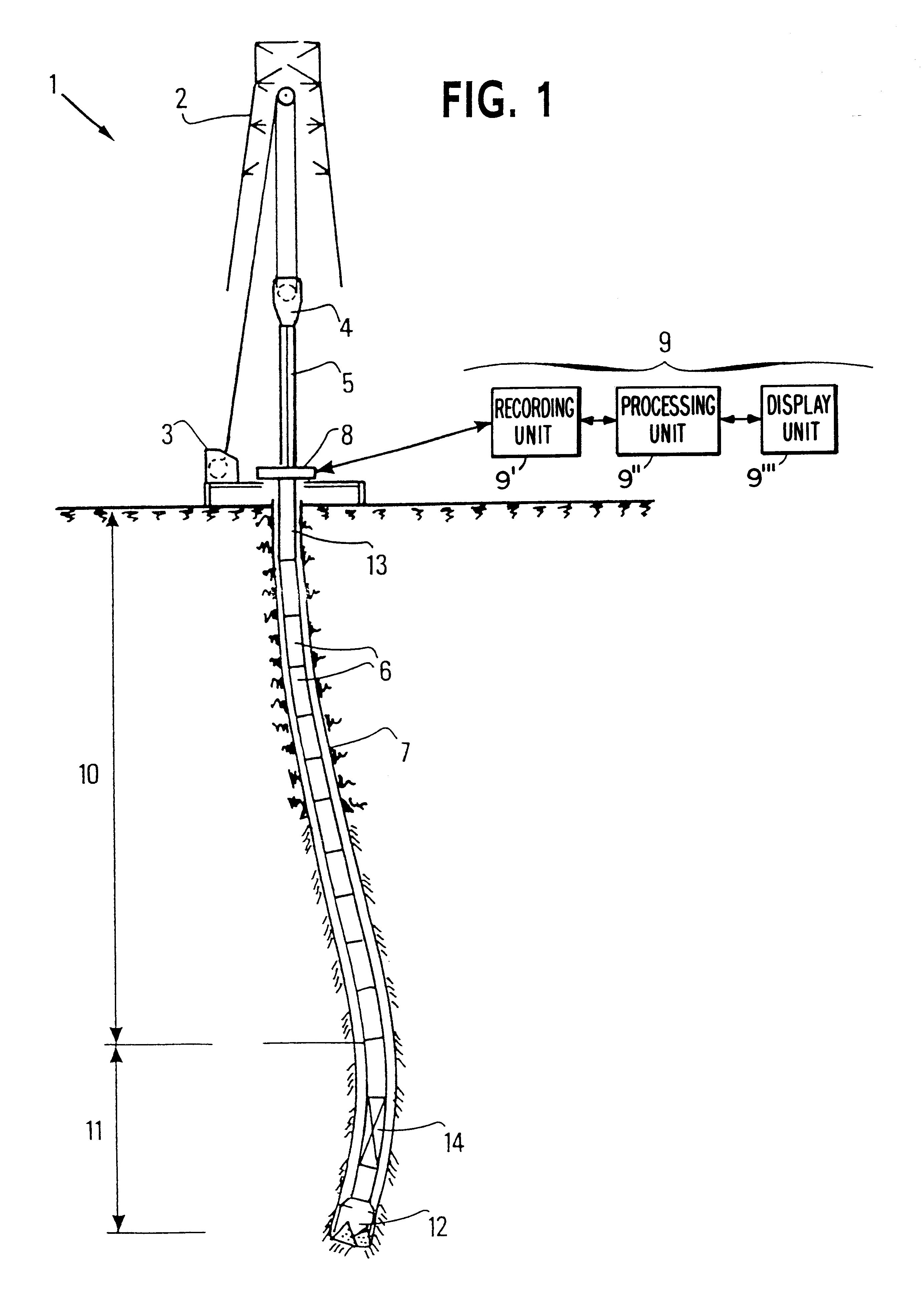
FIG. 1 illustrates a drilling rig in which the invention is implemented. The surface installation comprises a hoisting unit 1 including a hoisting tower 2, a winch 3 allowing displacement of a pipe hook 4. A device 5 for rotating the drill string is placed in the well 7 below the pipe hook 4 The device can be a kelly type device coupled to a rotary table 8 and a mechanical driver, or a power swivel type driver is directly suspended from the hook and longitudinally guided in the tower.

Drill string 6 conventionally has drillpipes 10, including a part 11 commonly referred to as BHA (Bottom Hole Assembly), mainly comprising drill collars and a drill bit 12 in contact with the formation during drilling. Well 7 is filled with drilling fluid which circulates from the surface to the bottom through the inner channel of the drill string and back to the surface through the annular space between the well walls and the drill string.

To implement the invention, an instrumented sub 13 is interposed...


PUM


Abstract

The present invention is a system and method for generating an alarm relative to effective longitudinal behavior of a drill bit fastened to the end of a drill string driven in rotation in a well by a driving device situated at the surface, using a physical model of the drilling process based on general mechanics equations. The following steps are carried out: the model is reduced so to retain only pertinent modes, at least two values Rf and Rwob are calculated, Rf being a function of the principal oscillation frequency of weight on hook WOH divided by the average instantaneous rotating speed at the surface, Rwob being a function of the standard deviation of the signal of the weight on bit WOB estimated by the reduced longitudinal model from measurement of the signal of the weight on hook WOH, divided by the average weight on bit WOB0, defined from the weight of the string and the average weight on hook. Any danger from the longitudinal behavior of the drill bit is determined from the values of Rf and Rwob.

Description

1. Field of the InventionThe present invention relates to measurement during drilling and in particular to measurements relative to the behaviour of a drill bit fastened to the end of a drill string.2. Description of the Prior ArtThere are well-known measuring techniques for acquisition of information relative to the dynamic behaviour of drill strings, using a series of bottomhole pickups connected to the surface by an electric conductor. In French Patent Application 92-02,273, two series of measuring pickups connected by a logging type cable are used, one being situated at the well bottom, the other at the top of the drill string. However, the presence of a cable along the drill string interferes with the actual drilling operations.French Patents 2,645,205 and 2,666,845 describe surface devices placed at the top of the string, which determine certain drilling dysfunctions according to surface measurements, but without taking physically account of the dynamic behaviour of the string...

Claims


Application Information

Patent Timeline
IPC IPC(8): E21B44/00
CPCE21B44/00
Inventor REY-FABRET, ISABELLEDESPLANS, JEAN-PIERRE
Owner INST FR DU PETROLE
Why Eureka
Try Eureka