Screening device and apparatus including same

a technology of a screen and a screen body, which is applied in the direction of screening, surface mining, and screening, etc., can solve the problems of obstructing material trapped, clogging of the screen opening in the grizzly, and affecting the removal of wash material

Inactive Publication Date: 2002-04-02
SORD TECH
View PDF28 Cites 13 Cited by
  • Summary
  • Abstract
  • Description
  • Claims
  • Application Information

AI Technical Summary

Benefits of technology

The tines may be movably supported on the support means so as to be capable of deflection upon encountering an unmanagable obstruction such as a large boulder which can neither be moved nor fragmented. This allows the tines to pass the unmanagable obstruction without damage.
The introduction of water, preferably at high pressure, into the zone may also assist in formation of the slurry or indeed to form the slurry in circumstances where the underground stream is inactive.
The recovery head may also have a re arward surface which tapers downwardly and rearwardly to a trailing edge. The trailing edge may provide a blade which facilitates passage of the recovery head through the underground zone on movement of the recovery head in the reverse direction. The rearward surface may have a second screening device according to the invention located in or otherwise associated with it.
The tines of one or more of the various screening devices incorporated in the recovery head may provide traction for propelling the recovery head through the underground zone.

Problems solved by technology

In some situations, the screen openings in grizzlys can become clogged by material obstructing the openings.
The obstructing material may be trapped in the screen openings or may simply accumulate on the intake side of the screen openings.
Removal of wash material does, however, present considerable difficulties owing to its irregular composition and the uneven nature of the bedrock beneath it.
It is the presence of the rocks and boulders in the wash material which presents a particular difficulty.
Similarly, marine deposits may be too deep for conventional mining operations.
The obstructions may include obstructing material temporarily trapped in the screen openings and obstructing material accumulating on the first side of the screen.

Method used


Image

  • Screening device and apparatus including same
  • Screening device and apparatus including same
  • Screening device and apparatus including same

Examples


Embodiment Construction

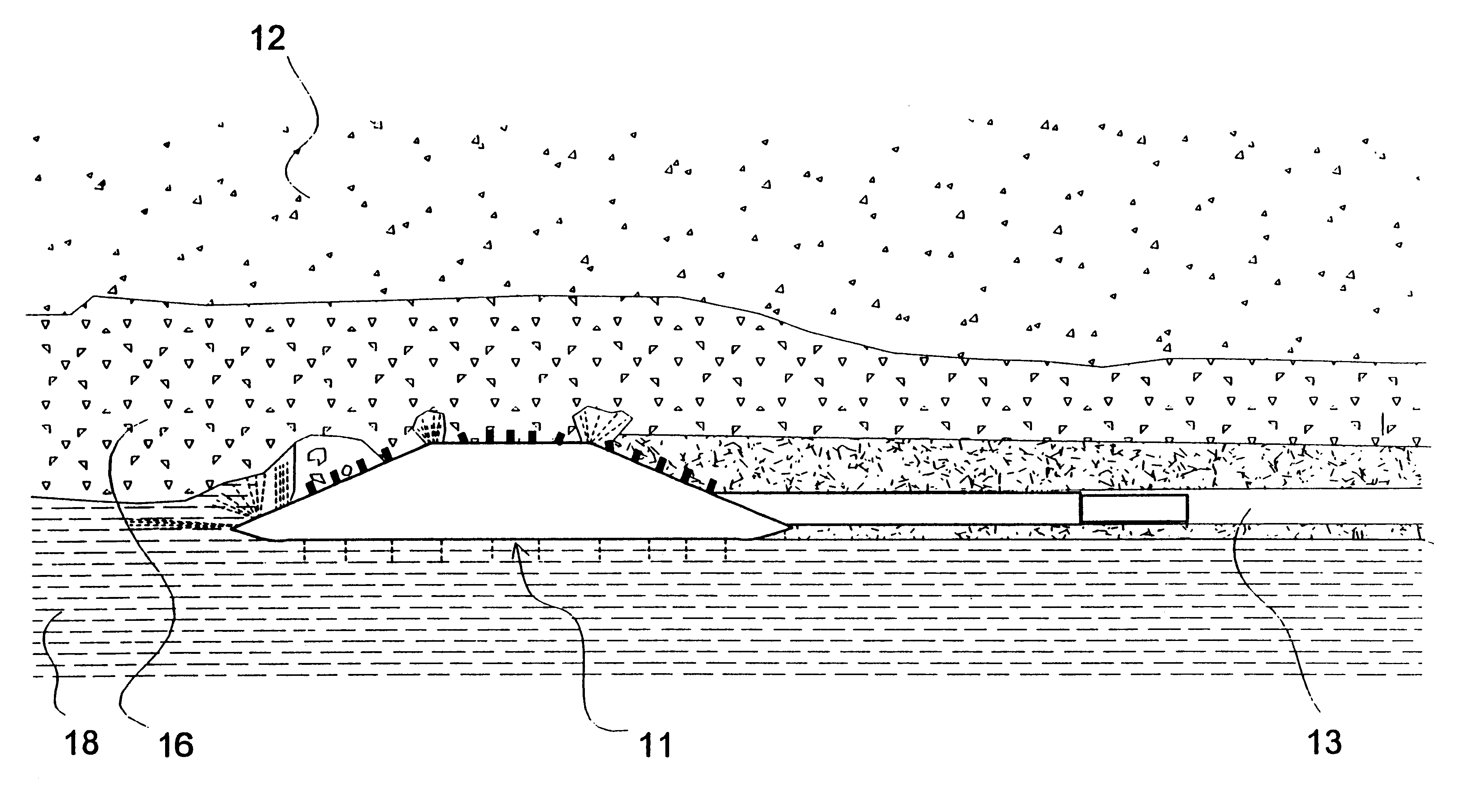
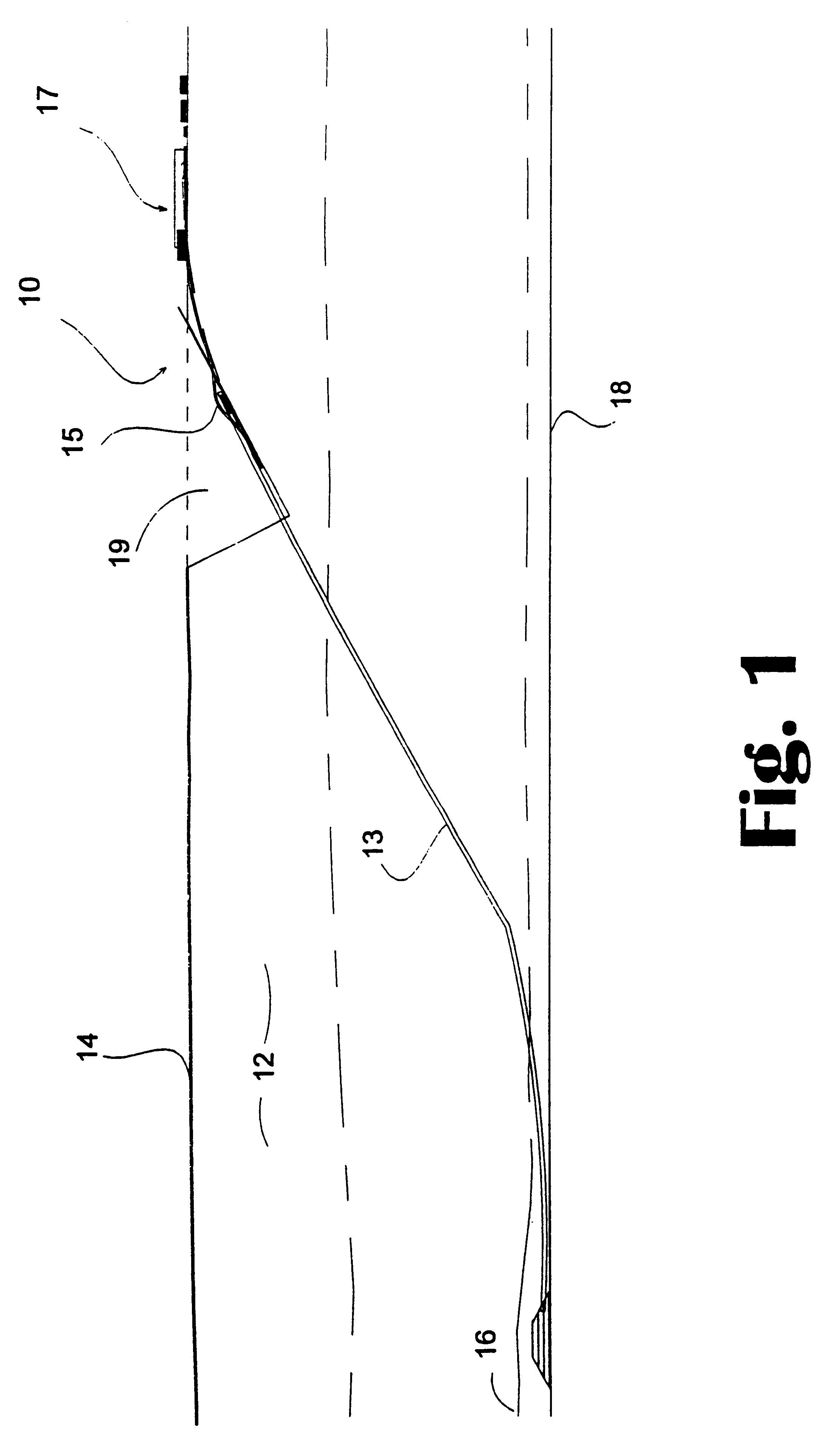
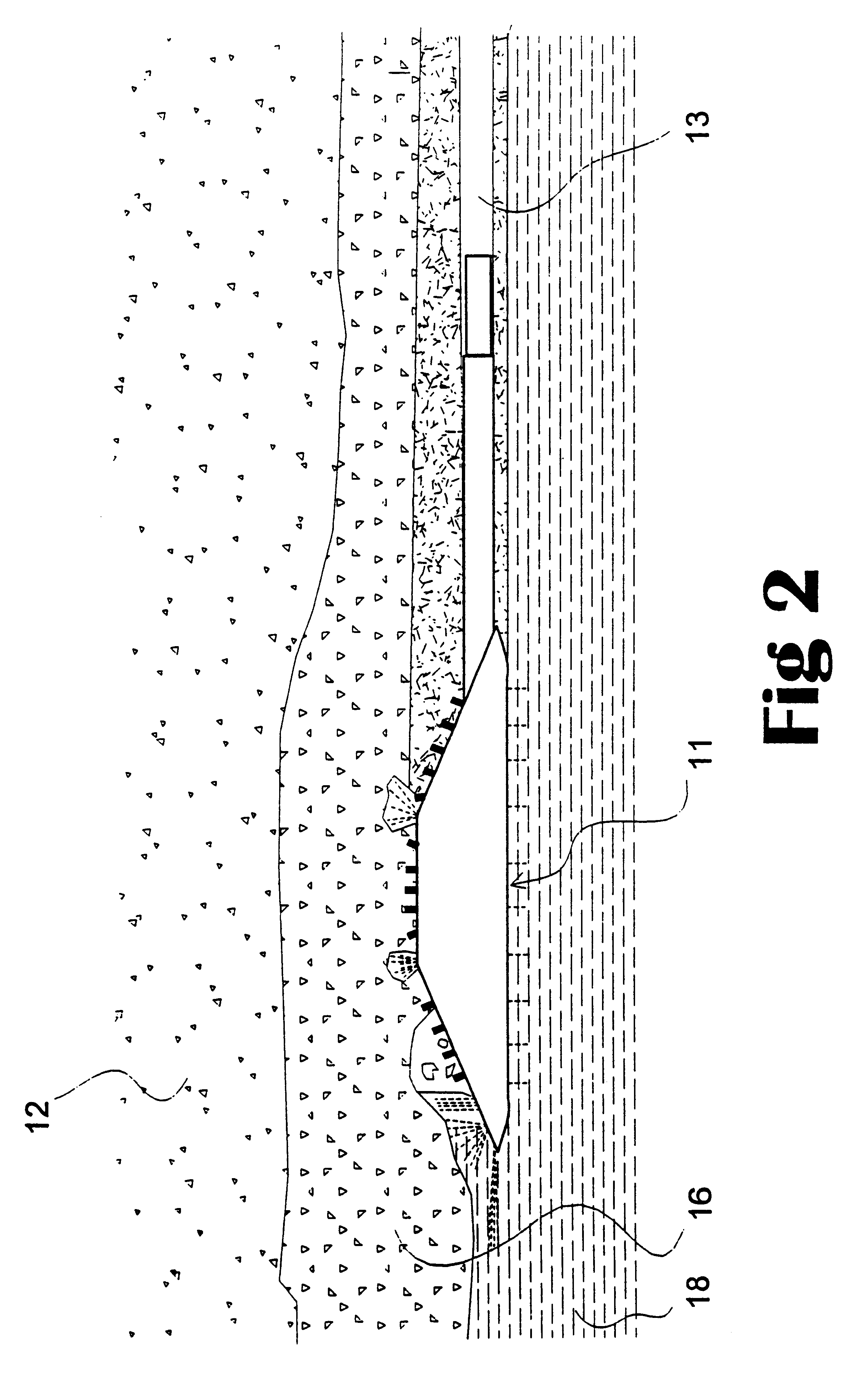
Referring to FIGS. 1 to 15 of the drawings, the first embodiment is directed to an underground mining apparatus 10 for recovering materials from normally inaccessible underground formations such as deep leads covered by an overburden of mud, sand and / or basalt. The apparatus is particularly suitable for recovery of metallic particles such as gold, diamonds, heavy metals and all alluvials present in such underground formations.

The wash of an underground stream (either active or dry) may be rich in gold bearing particles where the stream flows over bedrock in gold-bearing areas. The underground mining apparatus 10 according to the embodiment provides a way for accessing and recovering such particles.

The mining apparatus 10 comprises a recovery head 11 adapted to operate in the wash of an underground stream for recovering the metallic particles and other particles of interest. The recovery head 11 is positioned at the lower end of a pipe string 13 which in use extends through the overb...


PUM


Abstract

A screening device including a screen having a first side for presentation to material to be screened and a second side, a plurality of screen openings in the screen extending between the first and second side thereof, a plurality of tines mounted on a support device disposed on the second side of the screen, each tine being moveable in a first direction along a path at least part of which includes one of the screen openings whereby the tine is receivable in and moveable along the screen opening, the tine extending beyond the first side of the screen for at least part of the movement thereof along the screen opening, the tines being moveably mounted on the support device for deflection away from said first direction while continuing to move in said first direction upon encountering an obstruction.

Description

This invention relates to a screening device and to apparatus employing such a screening device. The invention also relates to a method of recovering material from an underground location.BACKGROUND TO THE INVENTIONScreens are used for separating aggregate material according to size. One common form of screen is a grizzly which comprises a set of parallel bars in spaced apart relationship to provide elongate screen openings. In some situations, the screen openings in grizzlys can become clogged by material obstructing the openings. The obstructing material may be trapped in the screen openings or may simply accumulate on the intake side of the screen openings.The present invention seeks to provide a screening device which has a screen and provision to remove obstructing material from screen openings within the screen.The screening device according to the invention has particular application in the recovery of material from an underground location. In such an application, the screeni...

Claims


Application Information

Patent Timeline
Patent Type & Authority Patents(United States)
IPC IPC(8): B07B1/12B07B1/52B07B1/46E02F3/94E21C41/16E02F3/88E02F3/92E02F7/00E21C41/00B07B1/55
CPCB07B1/12B07B1/46B07B1/528B07B1/55E21C41/16E02F3/9281E02F3/94E02F7/005E02F3/9262B07B1/4609
Inventor GRAHAM, NEIL DERYCK BRAY
Owner SORD TECH
Why Eureka
Try Eureka