Alternator

a technology of alternators and windings, which is applied in the field of alternators, can solve the problems of inability to suppress the temperature increase the cooling of stator winding 52 to deteriorate, and the inability to achieve high outpu

Inactive Publication Date: 2002-04-02
MITSUBISHI ELECTRIC CORP
View PDF24 Cites 34 Cited by
  • Summary
  • Abstract
  • Description
  • Claims
  • Application Information

AI Technical Summary

Problems solved by technology

Thus, the heat dissipation of the coil ends including the electrically-insulative resin portions 25 is not uniform, causing the cooling of the stator winding 52 to deteriorate, and one problem has been that temperature increases in the stator winding 52 cannot be suppressed.
Because the turn portions of the strands of wire 56 constituting the coil ends are not aligned so as to be stacked in the circumfer

Method used


Image

  • Alternator
  • Alternator
  • Alternator

Examples


embodiment 1

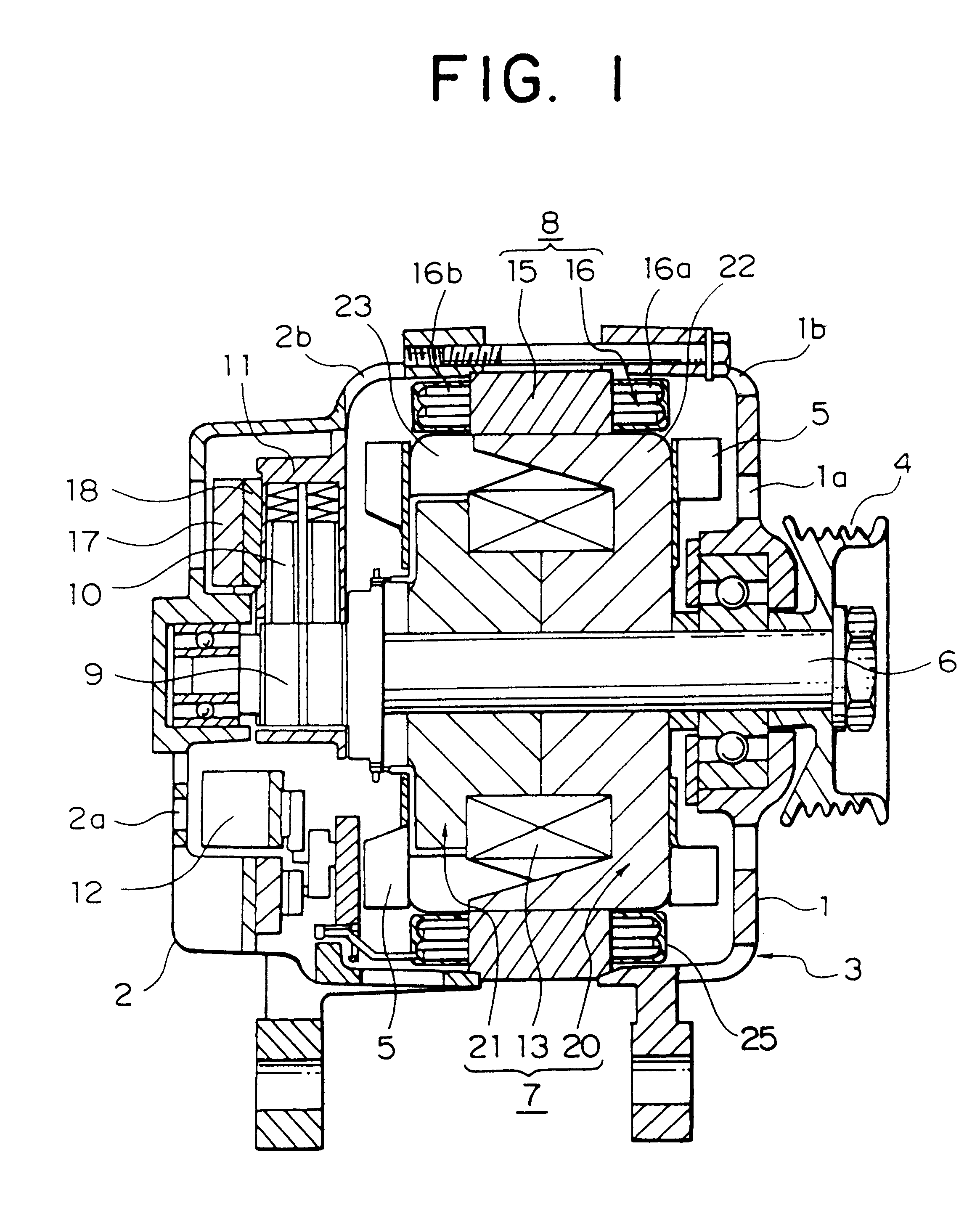
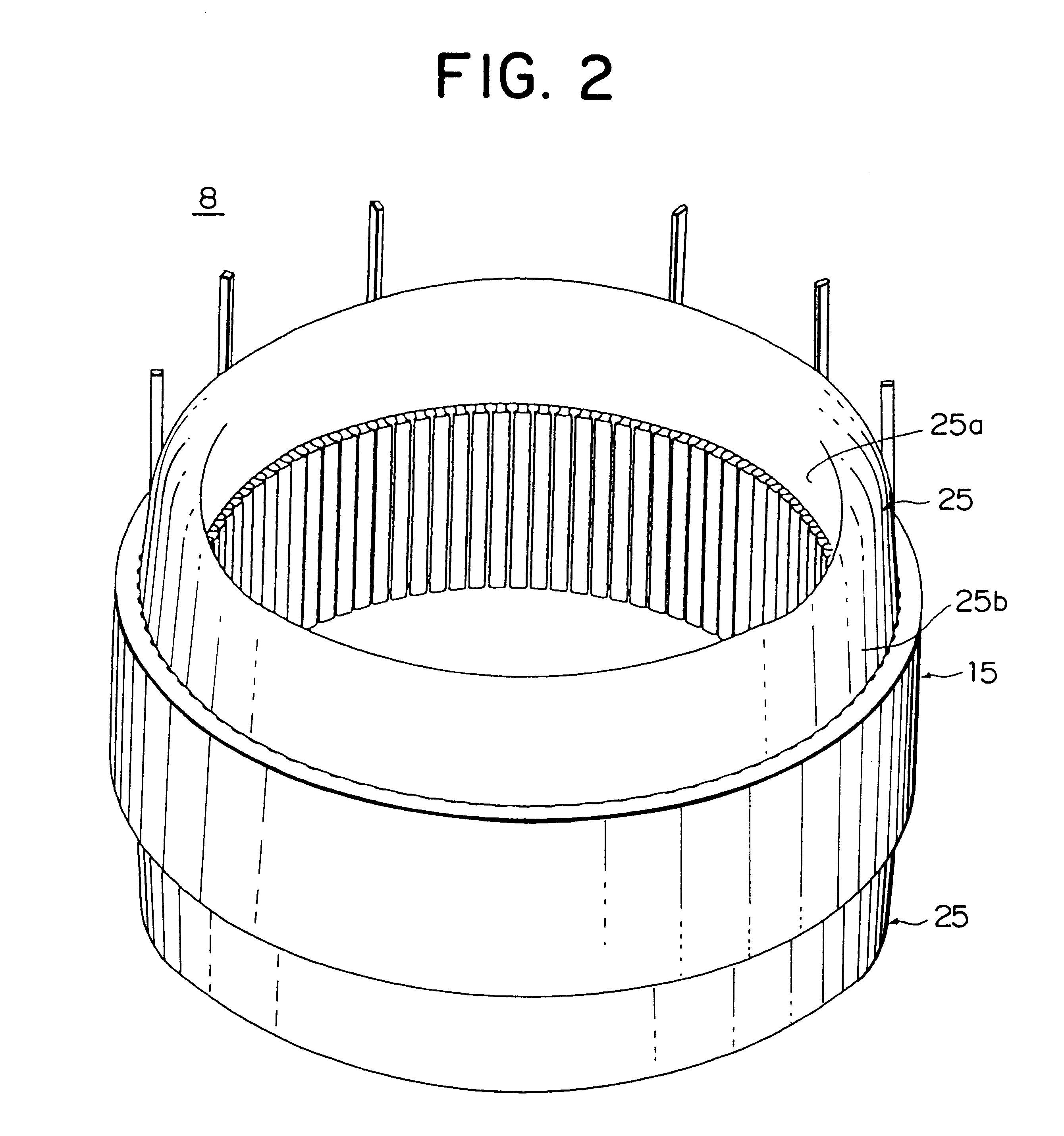
FIG. 1 is a cross section showing a construction of an automotive alternator of the present invention, FIG. 2 is a perspective showing a stator of this automotive alternator, FIG. 3 is an end elevation explaining connections in one stator winding phase group in this automotive alternator, FIG. 4 is a perspective explaining a stator winding mounted into the stator of this automotive alternator, FIG. 5 is a circuit diagram for this automotive alternator, FIGS. 6 and 7 are diagrams explaining the manufacturing process for wire-strand groups constituting part of the stator winding used in this automotive alternator, FIGS. 8A and 8B are an end elevation and a plan, respectively, showing an inner-layer wire-strand group constituting part of the stator winding used in this automotive alternator, FIGS. 9A and 9B are an end elevation and a plan, respectively, showing an outer-layer wire-strand group constituting part of the stator winding used in this automotive alternator, FIG. 10 is a per...

embodiment 2

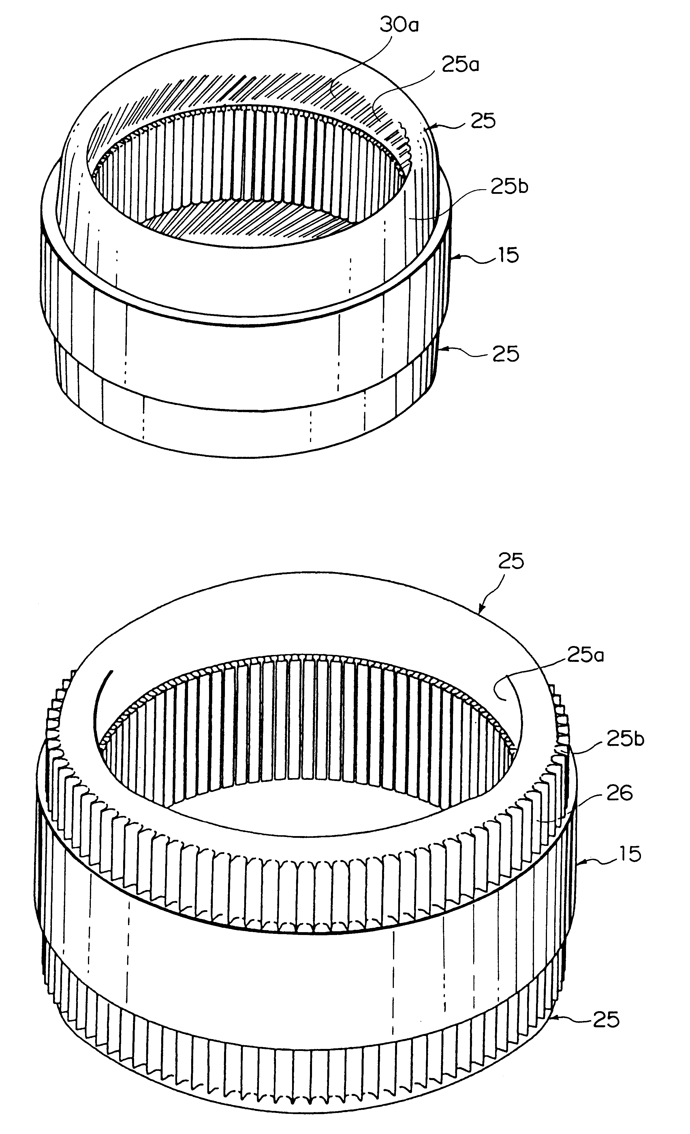
In Embodiment 2, as shown in FIG. 15, the bracket-facing surfaces 25b of the electrically-insulative resin portions 25 are disposed in close contact with inner wall surfaces of the front and rear brackets 1 and 2 of the rotor 8. Moreover, the rest of the construction is the same as in Embodiment 1 above.

According to Embodiment 2, because the bracket-facing surfaces 25b of the electrically-insulative resin portions 25 are disposed in close contact with inner wall surfaces of the front and rear brackets 1 and 2, heat generated in the coil ends 16a and 16b is efficiently transferred to the low-temperature brackets 1 and 2 through the electrically-insulative resin portions 25, improving the cooling of the stator winding 16 and enabling reductions in the size of the alternator proportionate to the reductions in gaps between the electrically-insulative resin portions 25 and the inner wall surfaces of the brackets 1 and 2.

embodiment 3

In Embodiment 3, as shown in FIG. 16, some outer surfaces (surfaces facing the rotor 7) of the turn portions 30a of the strands of wire 30 constituting the inner layer are positioned in the same plane as the rotor-facing surfaces 25a of the electrically-insulative resin portions 25 so as to be exposed. Moreover, the rest of the construction is the same as in Embodiment 1 above.

In Embodiment 3, because the cooling air contacts the exposed surfaces of the turn portions 30a of the strands of wire 30, heat generated in the coil ends 16a and 16b is efficiently radiated from the exposed surfaces of the turn portions 30a, improving the cooling of the stator winding 16.

Here, if the strands of wire 30 are formed with a rectangular cross section, it is easy to define the plane in which the strands of wire are exposed on the rotor-facing surfaces 25a of the electrically-insulative resin portions 25, but even if the strands of wire have a circular cross section, the same effect can be achieved ...


PUM


Abstract

An alternator includes a rotor for forming north-seeking (N) and south-seeking (S) poles about a rotational circumference, a stator including a stator core disposed facing the rotor, and a stator winding installed in the stator core, a bracket supporting the rotor and the stator, and a cooling means for cooling the stator winding by moving together with the rotor and generating a flow of cooling air inside the bracket, wherein the stator core includes a laminated core formed with a number of slots extending axially at a predetermined pitch in a circumferential direction, the stator winding includes a number of winding sub-portions in each of which a long strand of wire is wound so as to alternately occupy an inner layer and an outer layer in a slot depth direction within the slots at intervals of a predetermined number of slots, the strand of wire folding back outside the slots at first and second axial end surfaces of the stator core to form turn portions, the turn portions align in a circumferential direction to constitute coil ends, an electrically-insulative resin portion is disposed so as to completely cover the coil ends, and at least one surface of the electrically-insulative resin portion selected from a rotor-facing surface and a bracket-facing surface is formed into a smooth surface.

Description

1. Field of the InventionThe present invention relates to an alternator driven by an internal combustion engine, for example, and in particular, relates to a stator construction for an automotive alternator mounted to an automotive vehicle such as a passenger car or a truck.2. Description of the Related ArtFIG. 22 is a cross section showing a conventional automotive alternator, and FIG. 23 is a perspective showing a stator of the conventional automotive alternator.In FIGS. 22 and 23, the automotive alternator is constructed by rotatably mounting a Lundell-type rotor 7 by means of a shaft 6 inside a case 3 constructed from an aluminum front bracket 1 and an aluminum rear bracket 2, and fastening a stator 50 to an inner wall of the case 3 so as to cover an outer circumferential side of the rotor 7.The shaft 6 is rotatably supported in the front bracket 1 and the rear bracket 2. A pulley 4 is fastened to a first end of this shaft 6 so that rotational torque from an engine can be transm...

Claims


Application Information

Patent Timeline
IPC IPC(8): H02K3/28H02K9/06H02K3/12H02K1/16H02K9/04H02K15/02H02K15/06H02K15/00H02K15/04H02K3/04H02K3/34H02K19/22
CPCH02K3/12H02K9/06H02K3/28H02K3/24H02K3/38
Inventor HIGASHINO, KYOKOADACHI, KATSUMI
Owner MITSUBISHI ELECTRIC CORP
Why Eureka
Try Eureka