Switching power supply with overcurrent protection and method

a technology of overcurrent protection and power supply, which is applied in the direction of power conversion systems, dc-dc conversion, instruments, etc., can solve the problems of large resistors, reduced power conversion efficiency of power supply, and generation of electric power loss

Inactive Publication Date: 2002-04-02
MURATA MFG CO LTD
View PDF1 Cites 55 Cited by
  • Summary
  • Abstract
  • Description
  • Claims
  • Application Information

AI Technical Summary

Problems solved by technology

However, in a switching power supply provided with such a conventional current detection circuit, since the current detection resistor (11) for detecting the output current to the load is disposed in a main current path, electrical power loss is generated at this current detection resistor and the power conversion efficiency of the power supply is reduced.
Furthermore, since heat is generated due to electrical power loss occurring at the current detection resistor, a large resistor must be used.
Accordingly, there are problems in that the overall power supply becomes large and cost reduction cannot be achieved.

Method used


Image

  • Switching power supply with overcurrent protection and method
  • Switching power supply with overcurrent protection and method
  • Switching power supply with overcurrent protection and method

Examples


Embodiment Construction

Hereinafter, the preferred embodiments of the present invention are explained in detail with reference to the drawings.

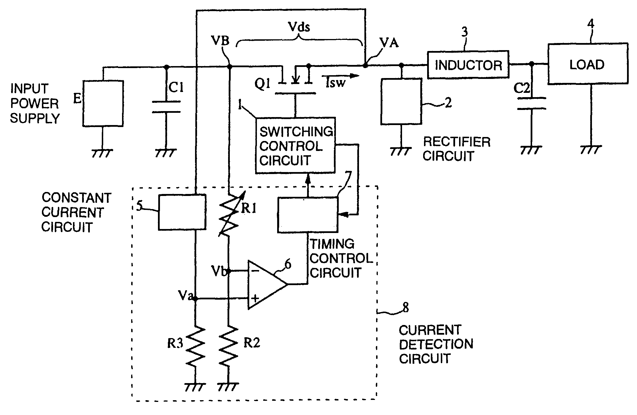
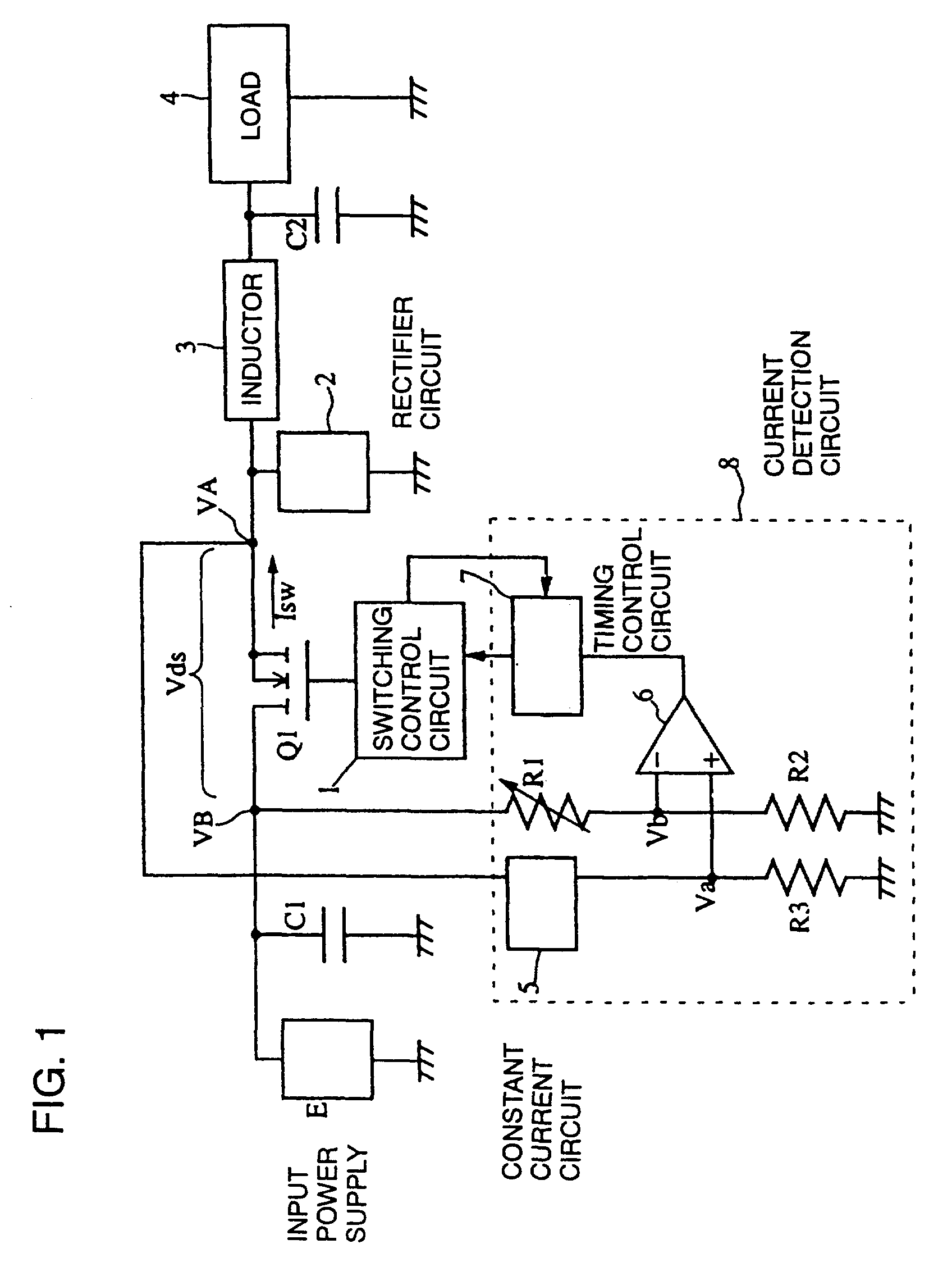
FIG. 1 shows the construction of a switching power supply according to an embodiment of this invention.

In FIG. 1, Q1 denotes a primary switching element, which is constructed using an N-channel type MOS-FET. A switching control circuit 10 performs on-off control by applying a control voltage to the gate of the primary switching element Q1. An input power supply E is connected to the drain of the primary switching element Q1. The input power supply E is connected in parallel with a capacitor C1. The source side of the primary switching element Q1 is connected to a rectifier smoothing circuit including a rectifier circuit 2, an inductor 3, and a capacitor C2. A resistance voltage divider consisting of a variable resistor R1 and a resistor R2 is provided between the drain of the primary switching element Q1 and the ground. A voltage divider consisting of a constant cur...


PUM


Abstract

A switching power supply comprises: a primary switching element for controlling an output voltage or an output current by switching the current of an input power supply circuit; a current detection circuit for detecting a current flowing through said primary switching element, based on the potential difference occurring across the ends of said primary switching element; and a switching control circuit for controlling said primary switching element so that the current does not exceed a predetermined value.

Description

1. Field of the InventionThe present invention relates to switching electrical power supplies, and more specifically, it relates to a switching power supply with overcurrent protection.2. Description of the Related ArtHitherto, a switching power supply has been provided with overcurrent protection in order to protect the switching power supply itself and a load when an excessive output current flows due to an overload state caused by the occurrence of a short circuit for some reason at the output side of the power supply.FIG. 4 shows a conventional switching power supply with such overcurrent protection. In FIG. 4, Q1 denotes a primary switching element, which is typically constructed using MOS-FET[s]. A switching control circuit 10 performs on-off control by applying a control voltage to the gate of the primary switching element Q1. An input power supply E is connected to the drain of the primary switching element Q1. The input power supply E is connected in parallel with a smoothi...

Claims


Application Information

Patent Timeline
Patent Type & Authority Patents(United States)
IPC IPC(8): H02M3/04H02M3/156H02M3/155
CPCH02M3/156H02M2001/0009H02M1/0009
Inventor MORISHITA, YASUNOBU
Owner MURATA MFG CO LTD
Why Eureka
Try Eureka