Electric machine

a technology of electric machines and motors, applied in the direction of dynamo-electric machines, vehicle sub-unit features, propulsion using engine-driven generators, etc., can solve the problems of requiring more space and more expensive hardware, and purely mechanical drive manufactur

Inactive Publication Date: 2002-04-16
SCHRODL MANFRED
View PDF26 Cites 174 Cited by
  • Summary
  • Abstract
  • Description
  • Claims
  • Application Information

AI Technical Summary

Problems solved by technology

The manufacture of the known electromechanical drives or purely mechanical drives, for example gears in which two different, usually independent speeds are required, is very complicated.
All the electric machines mentioned above have the disadvantage, however, that for the generation and

Method used


Image

  • Electric machine
  • Electric machine
  • Electric machine

Examples


Embodiment Construction

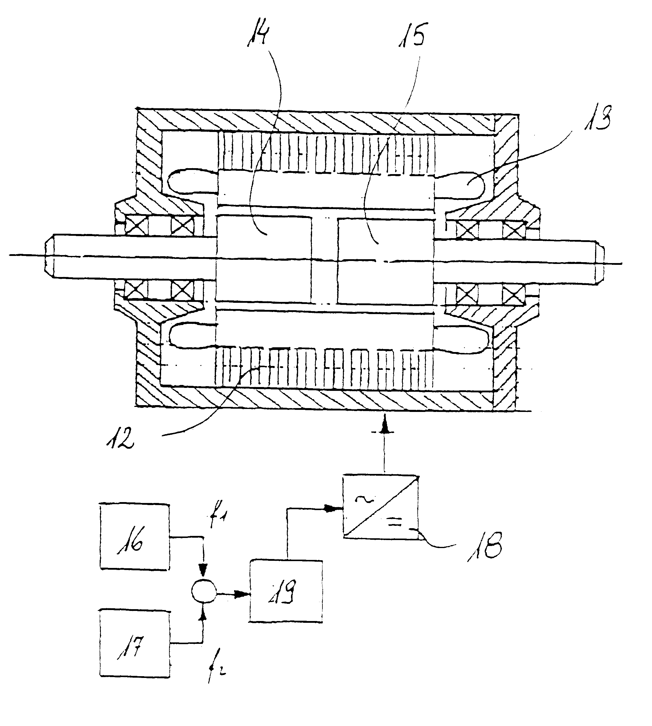
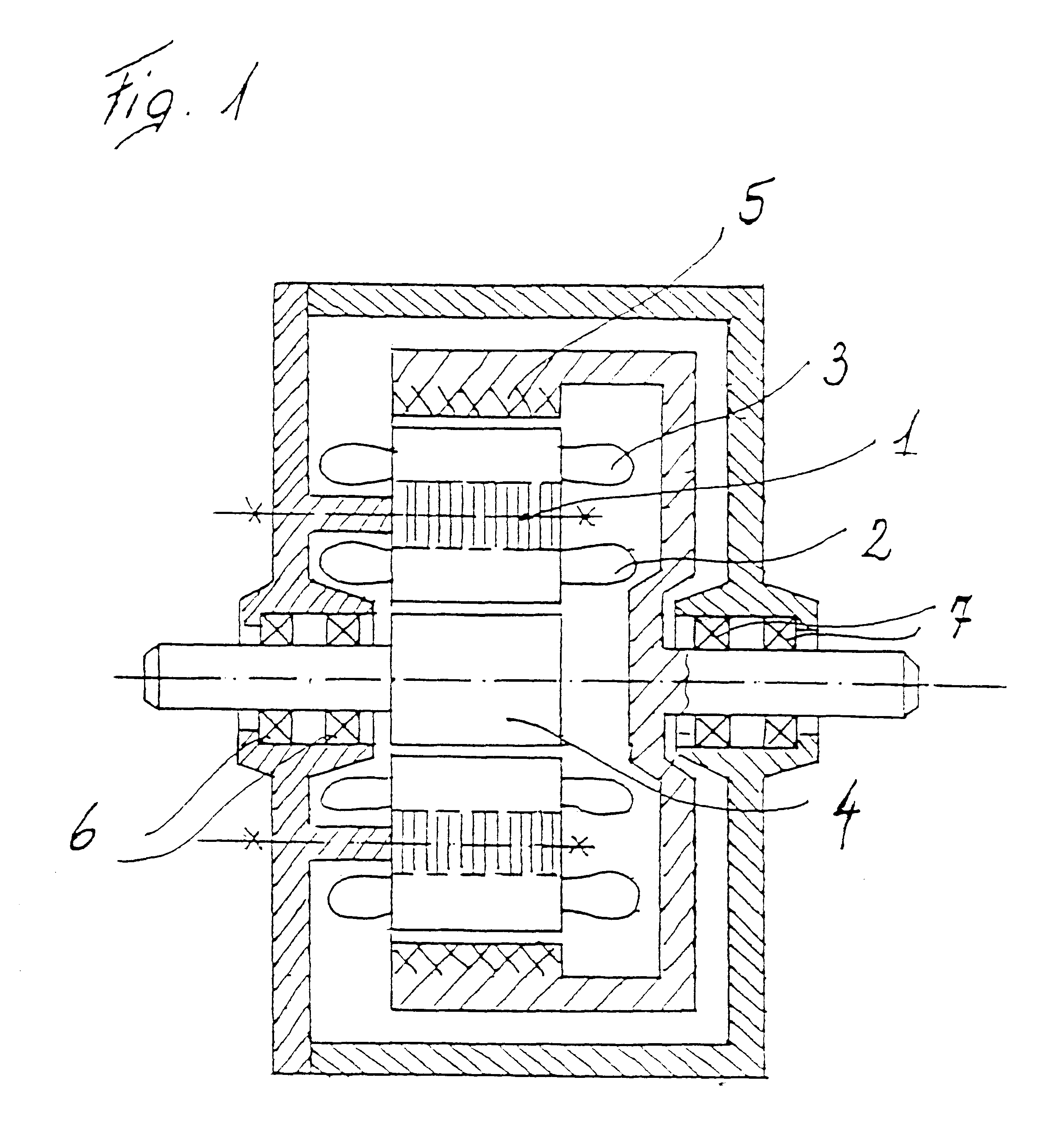
Basically, various desing variations from double rotor machines are possible. FIG. 1 shows a double rotor machine with one stator 1, which has two independent windings 2, 3.

In the cylindrical motor array, one winding 2 is on the inside of the stator 1 or the stator bore, and is designed as a groove or air-gap winding. The second winding 3 is positioned on the outside of the stator 1 as a groove or air-gap winding, whereby winding 2 interacts with a rotor 4 designed as an inner rotor, and winding 3 interacts with a rotor 5 designed as an outer rotor. The rotors 4, 5 can be designed with permanent magnet excitation, as cage rotors, with a reluctance structure, etc. The two rotors 4, 5 are arranged mechanically on one suitable bearing 6, 7 each according to the state of the art.

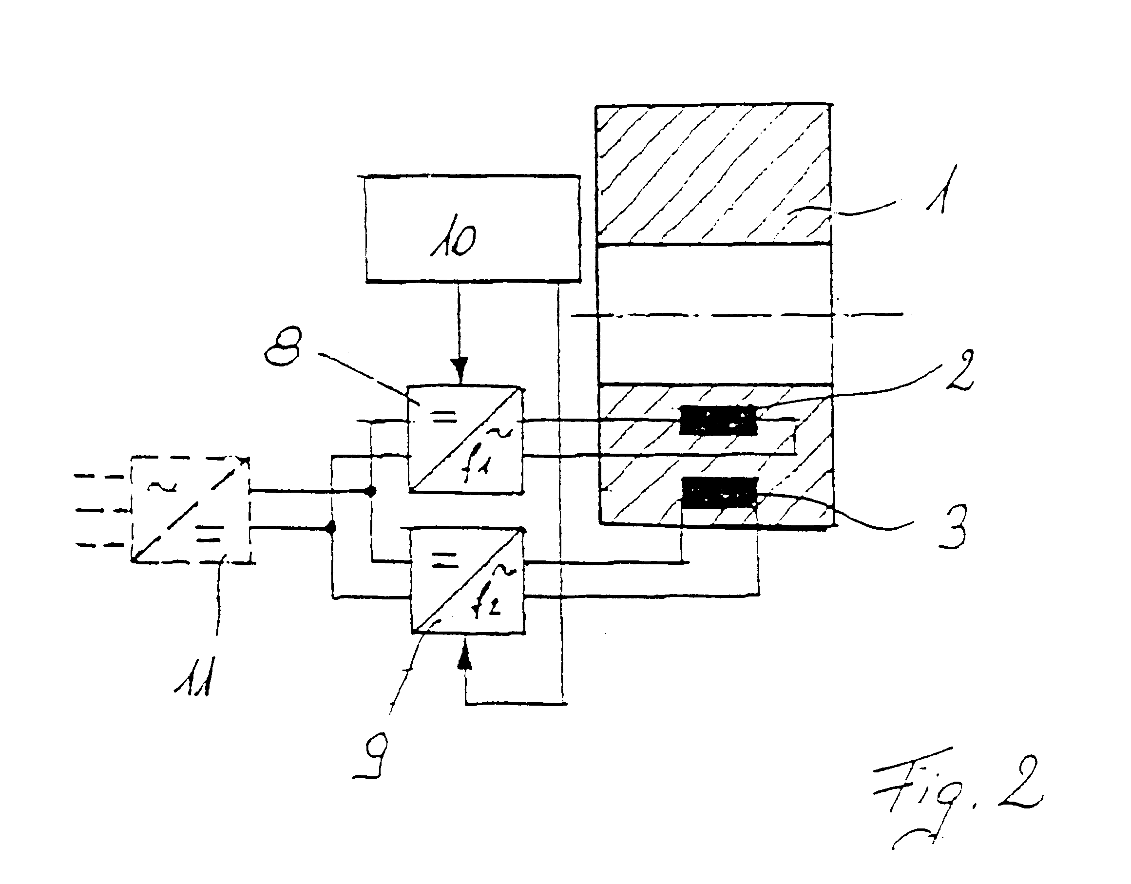
In accordance with FIG. 2, the two windings 2, 3 of the stator 1 are supplied from generally different power sources. The power sources are preferably rotary current inverters 8, 9 with variable frequency and ar...


PUM


Abstract

Electric rotary current machine that includes a casing and a stator fitted within the casing. The stator has at least one stator winding. At least two mechanically separate rotors are rotatably mountable within the casing and have a same axis of rotation. In this way, each rotor has electromagnetic interaction with the stator when the stator is electromagnetically active. The rotor speeds are the same or different. A motor control is arranged to control a supply to at least one of said at least one stator winding by superposition of at least two rotary field components, one for each rotor.

Description

1. Field of the InventionThe invention relates to an electric machine of the rotary current type, whereby in a casing a stator is fitted with at least one stator winding and at least two mechanically separate rotors, whereby the rotors have the same axis of rotation, and whereby each rotor has electromagnetic interaction with the electromagnetically active stator, whereby the rotor speeds may be the same or different.2. Discussion of Background InformationIt is known that rotary current machines can be used advantageously for electromechanical energy transformation. These are fitted with a stator and rotary current winding system through which electric current flows, and have interaction with a magnetic field that is created either by permanent magnets, by field windings in the case of synchronous machines, or by the stator winding itself in asynchronous and reluctance machines, or by a combination of these possibilities.The manufacture of the known electromechanical drives or purel...

Claims


Application Information

Patent Timeline
IPC IPC(8): H02K51/00H02K16/00H02K16/02
CPCH02K51/00H02K16/02H02K16/00B60Y2400/607B60L15/20B60L2220/12B60L2220/14B60L2220/16B60L2220/18B60L2220/42B60L2220/54B60L2240/421B60L50/10Y02T10/64Y02T10/7072Y02T10/72Y02T10/70
Inventor SCHRODL, MANFRED
Owner SCHRODL MANFRED
Why Eureka
Try Eureka