Direct-measured DLL circuit and method

a dll circuit and measurement circuit technology, applied in pulse manipulation, pulse technique, instruments, etc., can solve the problem that obtaining the correct adjustment of the feedback clock can be a time-consuming (or even perpetual) process

Inactive Publication Date: 2002-04-16
XILINX INC
View PDF6 Cites 37 Cited by
  • Summary
  • Abstract
  • Description
  • Claims
  • Application Information

AI Technical Summary

Problems solved by technology

Clearly, obtaining the correct adjustment for a feedback clock can be a time-consuming (or even perpetual) process, using known methods.

Method used


Image

  • Direct-measured DLL circuit and method
  • Direct-measured DLL circuit and method
  • Direct-measured DLL circuit and method

Examples


Embodiment Construction

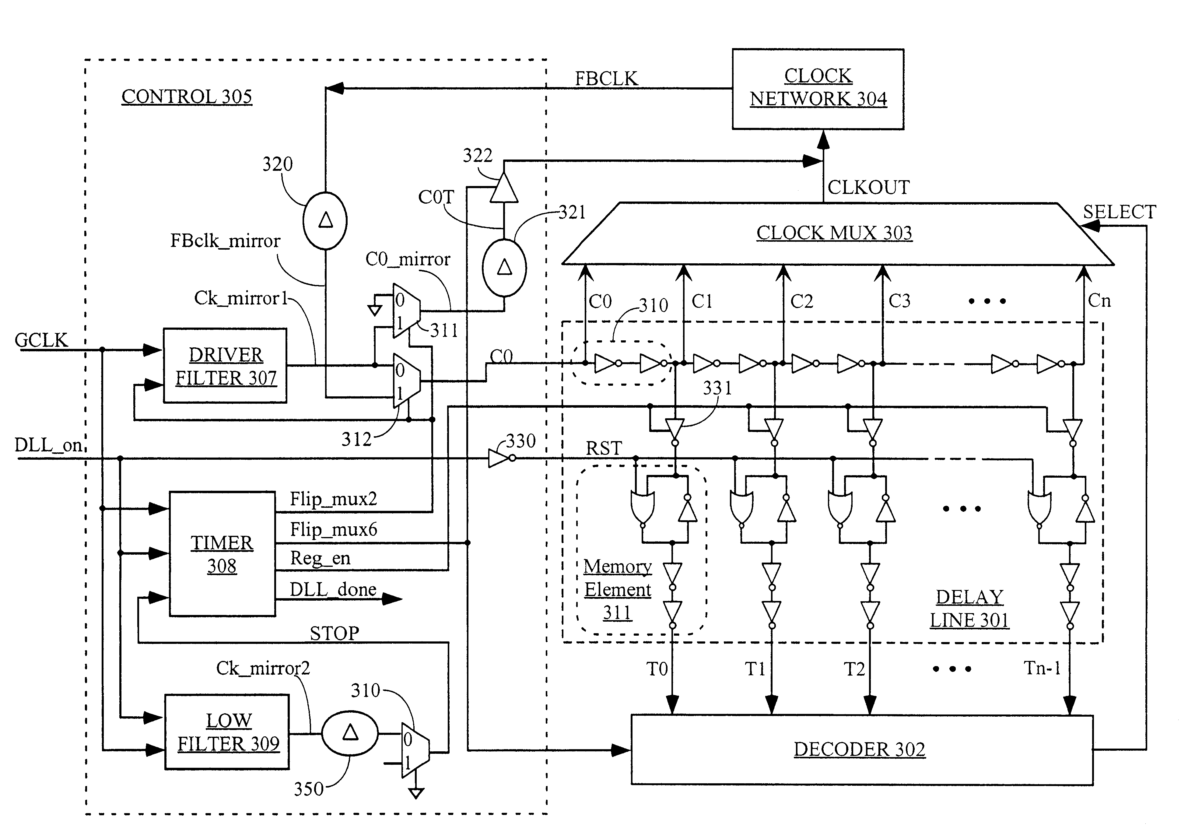
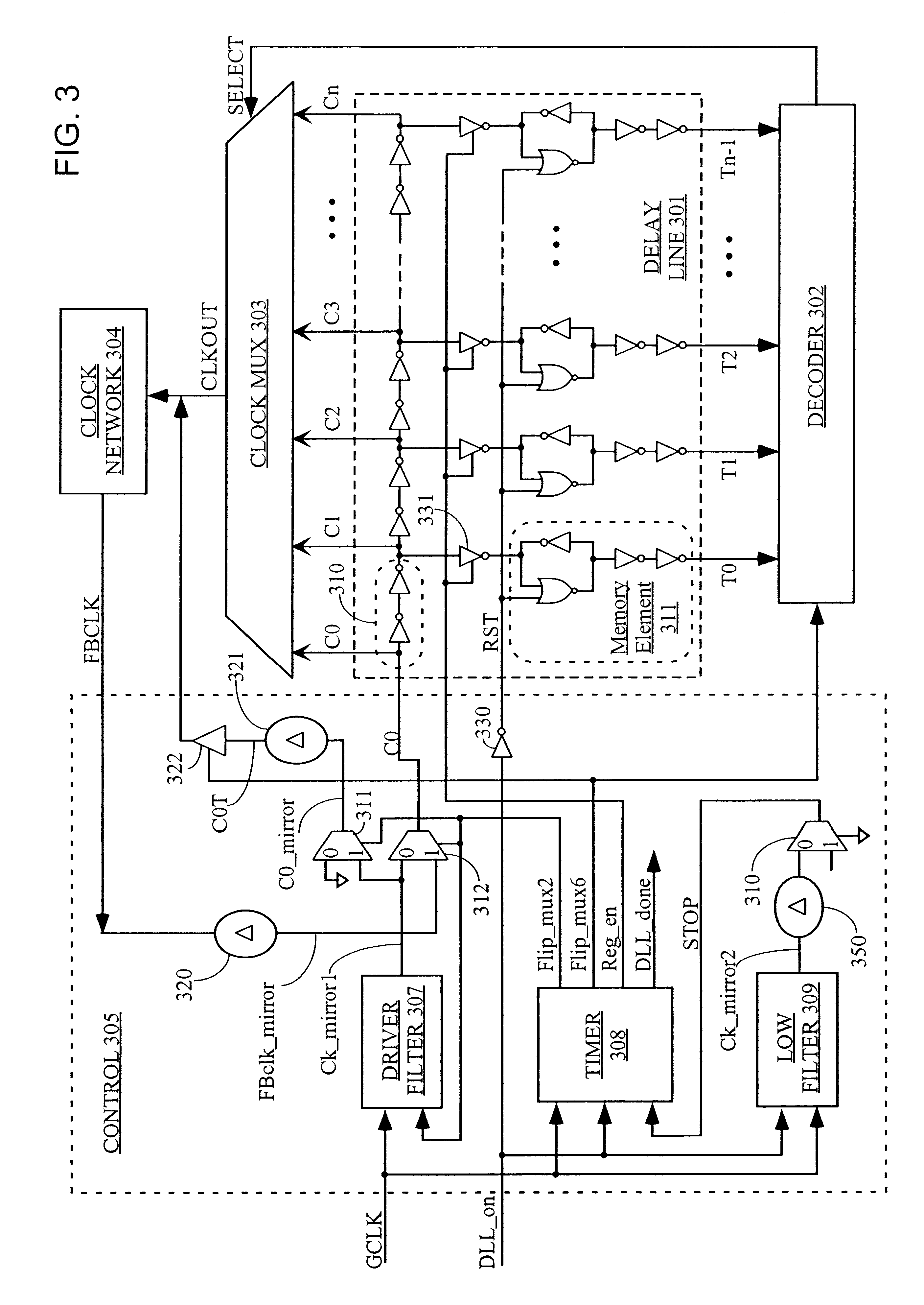
FIG. 3 shows a block diagram of a DLL circuit according to one embodiment of the invention. The DLL circuit of FIG. 3 includes a delay line 301, a decoder circuit 302, a clock multiplexer 303, a clock network 304 (generally located external to the DLL, but included in FIG. 3 for clarity), and a control circuit 305.

Clock network 304 provides a feedback clock signal FBCLK that drives both control circuit 305 and other circuits in the IC.

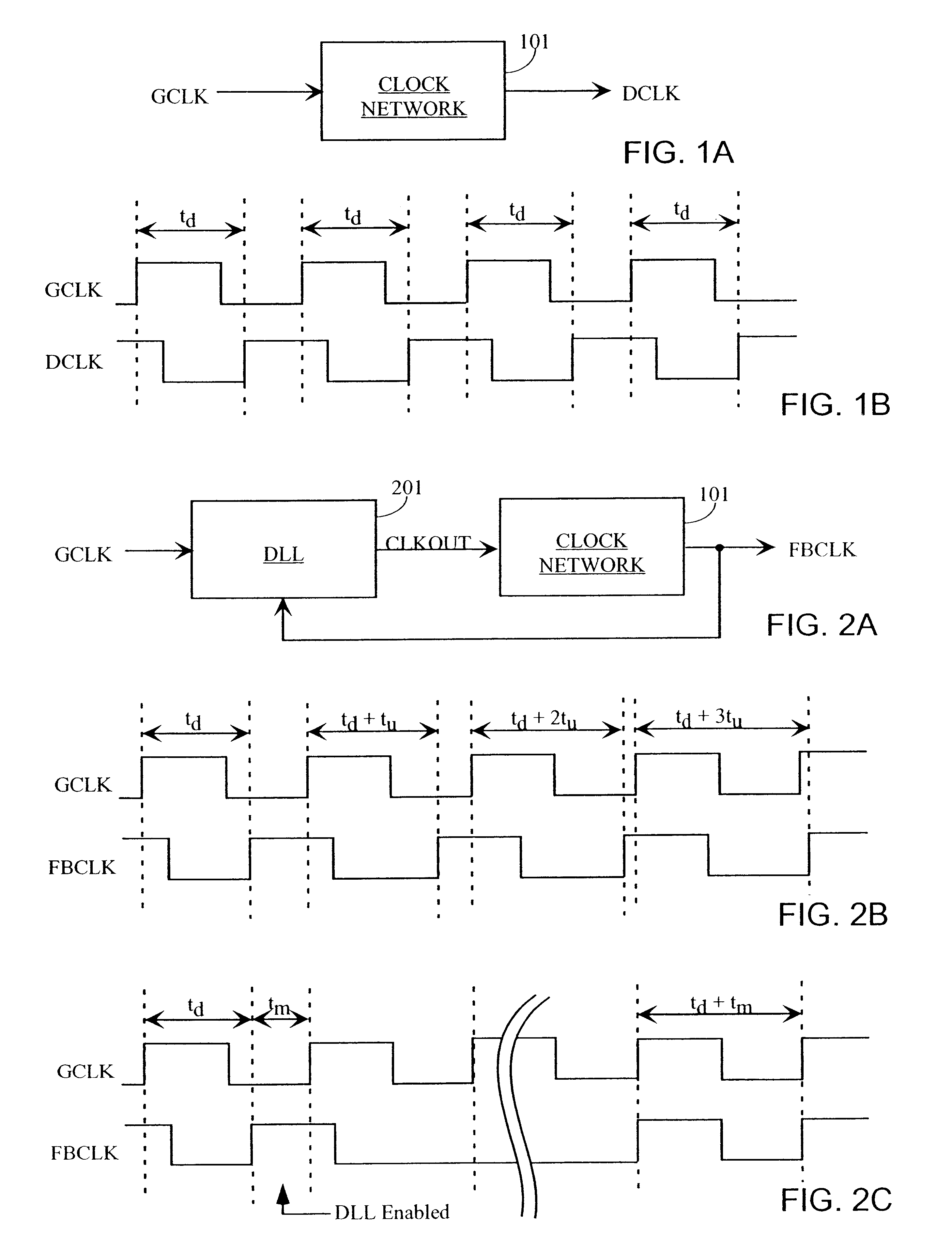
Delay line 301 is driven by control circuit 305, which provides to the delay line a signal C0 derived either from feedback clock signal FBCLK (in a first mode) or from input clock signal GCLK (in a second mode). Delay line 305 comprises a series of delay elements 310, each having a delay of one "unit delay". A unit delay can be any period of time appropriate to the application of the DLL circuit. For example, a unit delay can be measured in tens, hundreds, or thousands of picoseconds, or even longer periods of time, particularly for non-IC applications...


PUM


Abstract

A delay-lock loop (DLL) circuit and method that accept an input clock signal and a feedback clock signal, and provide the necessary additional delay to synchronize the feedback clock signal to the input clock signal. A single synchronization step is sufficient, provided that the frequency of the input clock signal is stable. Further, only one delay line is required to implement the DLL circuit. Therefore, the DLL of the present invention is both quick to "lock in" a clock signal and efficient in the use of hardware resources. Further, the present DLL is very accurate, because the same delay line is used to calculate the necessary additional delay and to generate the output clock signal.

Description

The invention relates to integrated circuits (ICs). More particularly, the invention relates to a delay-lock loop (DLL) circuit and method for an IC.Clock signals are used in virtually every IC and electronic system to control timing. For example, every time there is a rising edge on a clock signal, all the flip-flops in a circuit may change state. Clearly, clocks are often heavily loaded signals, and may be bussed throughout a very large IC. Even with specially-designed global buffers, there is typically a delay between the clock edge received by the IC at the pad, and the clock edge received by the last-served flip-flop on the IC (i.e., between the "input clock signal" and the "destination clock signal"). This delay, designated herein as t.sub.d, may cause difficulties in interfacing between ICs, or simply slow down the overall system speed. Input data may be provided in synchronization with the input clock signal, while output data is typically provided in synchronization with th...

Claims


Application Information

Patent Timeline
Patent Type & Authority Patents(United States)
IPC IPC(8): H03L7/085H03K5/13H03L7/08H03L7/081H03K5/00
CPCH03K5/00006H03K5/131H03K5/133H03L7/085H03L7/0814
Inventor NGUYEN, ANDY T.
Owner XILINX INC
Why Eureka
Try Eureka