
Portable, combustion engine powered cutting or sawing machine

a technology of cutting or sawing machine and combustion engine, which is applied in the direction of metal sawing device, metal sawing apparatus, manufacturing tools, etc., can solve the problems of not having hydraulic power packs, and not having such mobile power packs

Inactive Publication Date: 2002-04-23
HUSQVARNA AB
View PDF14 Cites 64 Cited by
  • Summary
  • Abstract
  • Description
  • Claims
  • Application Information

AI Technical Summary

Benefits of technology

Hydraulic motor powered cutting machines, however, have one deficiency; they need to have a hydraulic power pack. It is true there exist portable power packs with a hydraulic pump, which can be powered by a combustion engine or by an electric motor, but in many situations there is no hydraulic power packs available or it is not possible to have such mobile power packs. Typical situations of that kind are in connection with accidents, fires, and on remote places and also, more generally, in regions having a low developed infrastructure. It has therefore existed a long felt demand for a combustion engine powered ring cutter with features which from an ergonomic and safety point of view which are equally or at least comparably good as those of hydraulic motor powered ring cutters and with performances which also in other aspects are good or very good.

Problems solved by technology

Hydraulic motor powered cutting machines, however, have one deficiency; they need to have a hydraulic power pack.
It is true there exist portable power packs with a hydraulic pump, which can be powered by a combustion engine or by an electric motor, but in many situations there is no hydraulic power packs available or it is not possible to have such mobile power packs.
A slender, i.e. a comparatively elongated and slim design, however, also may mean fragility.

Method used


Image

  • Portable, combustion engine powered cutting or sawing machine
  • Portable, combustion engine powered cutting or sawing machine
  • Portable, combustion engine powered cutting or sawing machine

Examples


Embodiment Construction

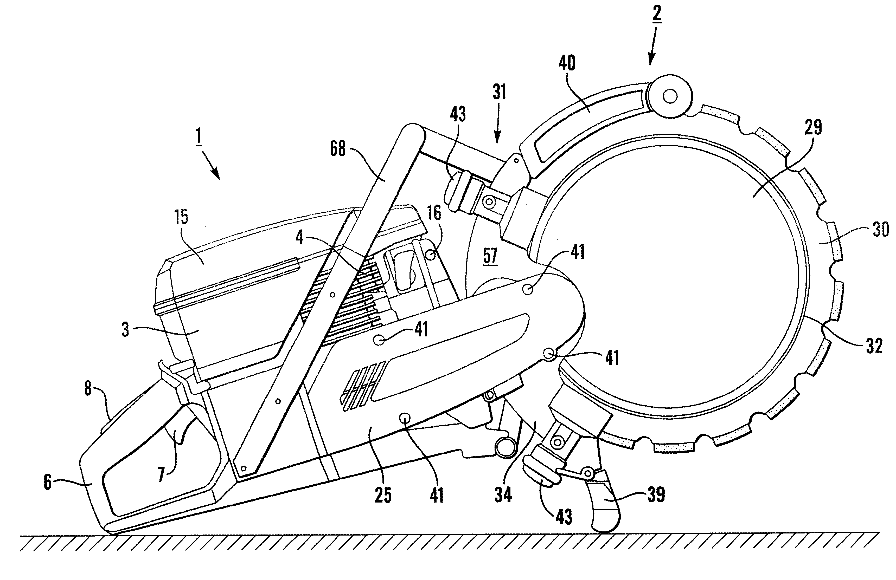
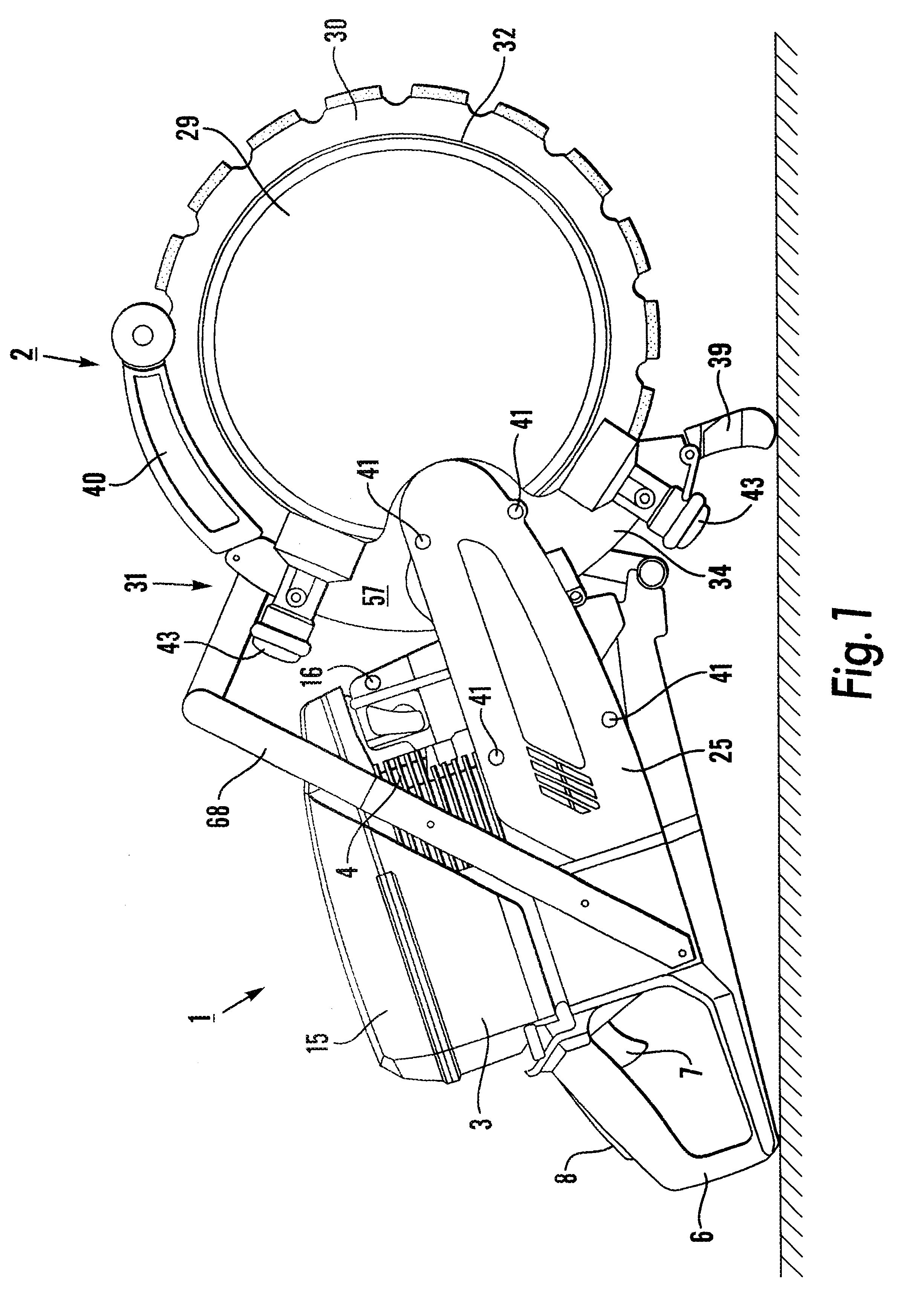
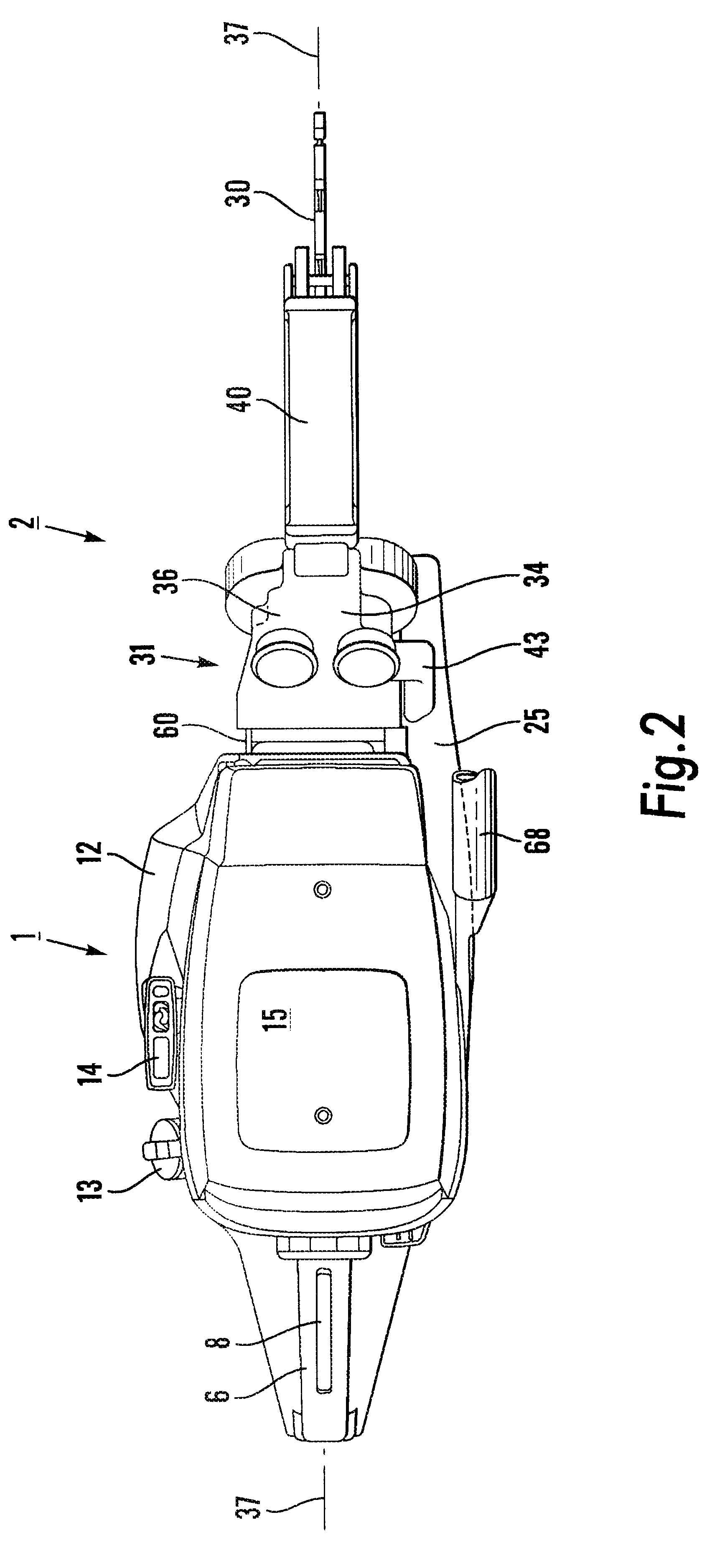
The ring cutter shown in the drawings has a rear part 1 and a front part 2. In the rear part 1 there is a motor housing 3 with a combustion engine 4, an engine block 5 with a crankcase, and a rear operating handle 6 with motor controls 7, 8. The motor housing 3 with engine and auxiliary elements has a general design which is known per se and which is employed in some existing cutting machines, which are powered by a combustion engine and in which the cutting disc is of a conventional type and is mounted on a projecting cutting arm, such as on the cutting machine that is marketed under the trade name PARTNER.RTM.K950.

On the right hand side of the engine block / crankcase 5 there is a drive wheel 10 for a driving belt 11, which is of the flat and broad, multi-grooved type which nowadays to a great extent is used in connection with motorcar engines for the drive of generators, water pumps, etc. and which can withstand substantially higher rates of rotation than conventional V-belts. The ...


PUM

PropertyMeasurementUnit
distanceaaaaaaaaaa
total dimensionsaaaaaaaaaa
fragilityaaaaaaaaaa

Abstract

A portable, combustion engine powered cutting or sawing machine comprises a rear part (1) with a motor housing (3) with a combustion engine (4), an engine block (5) with a crank house, and a front part (2) with an annular blade (30) and a blade holder (31). The blade is provided in / or adjacent to a center blade (37) of the machine. The engine block forms a central body in the machine, including portions of said body on both sides of said center plane, and the blade holder comprises a blade holder chassis (35), which is provided substantially on a first side of said center plane. The blade holder chassis is fixedly connected on one hand with the portion of the engine block, which is located on said first side of the center blade, and on the other hand with a portion which is located on a second, opposite side of the center plane.

Description

The invention concerns a portable, combustion engine powered cutting or sawing machine comprising a rear part with a motor housing with a combustion engine and an engine block with a crankcase, and a front part with an annular saw and a blade holder. The invention particularly concerns a cutting or sawing machine of the mentioned type with a rear operating handle on said rear part, and a power transmission which includes a driving belt and at least one drive wheel in the blade holder for the drive of the blade.PRIOR ARTA portable, combustion engine powered cutting or sawing machine is previously known through U.S. Pat. No. 4,352,241. It is a characterising feature of that machine that the rear part of the machine, including motor, operating handle and control means on one hand, and the front part of the machine with the cutting blade on the other hand, are pronouncedly displaced laterally relatively to one another, which is most clearly obvious in FIG. 1 and FIG. 2 in the patent doc...

Claims


Application Information

Patent Timeline
Patent Type & Authority Patents(United States)
IPC IPC(8): B23D47/12B23D47/00
CPCB23D47/123
Inventor CLAESSON, TORE
Owner HUSQVARNA AB
Learn More