Shape memory alloy wire actuator

Inactive Publication Date: 2002-04-23
ENERGY CONVERSION SYST HLDG
View PDF11 Cites 93 Cited by
  • Summary
  • Abstract
  • Description
  • Claims
  • Application Information

AI Technical Summary

Benefits of technology

It is an object of the present invention to provide a shape memory all

Problems solved by technology

The tension forces applied by the ends of the wires to opposite sides of the pulley pair resul

Method used


Image

  • Shape memory alloy wire actuator
  • Shape memory alloy wire actuator
  • Shape memory alloy wire actuator

Examples


Example

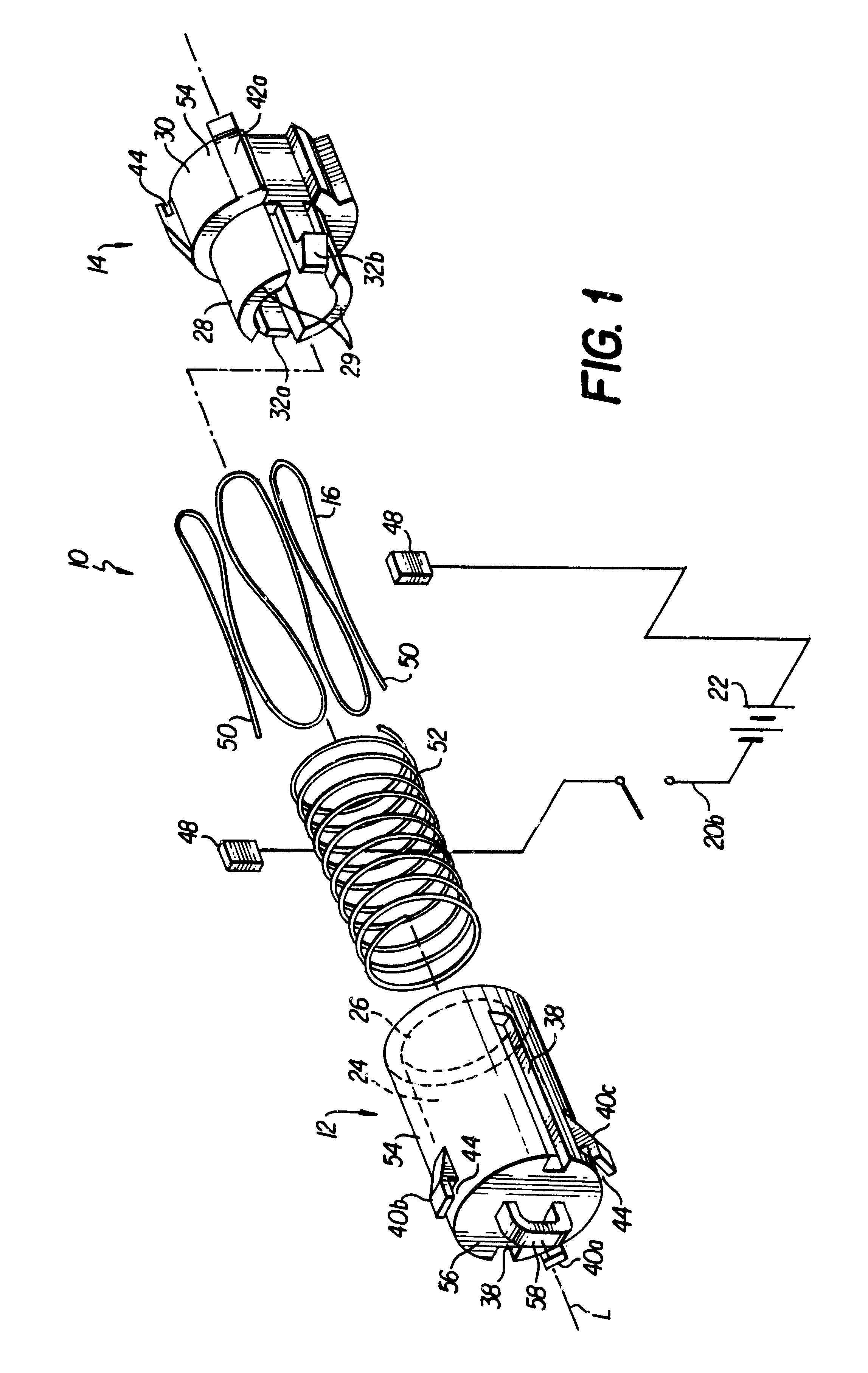
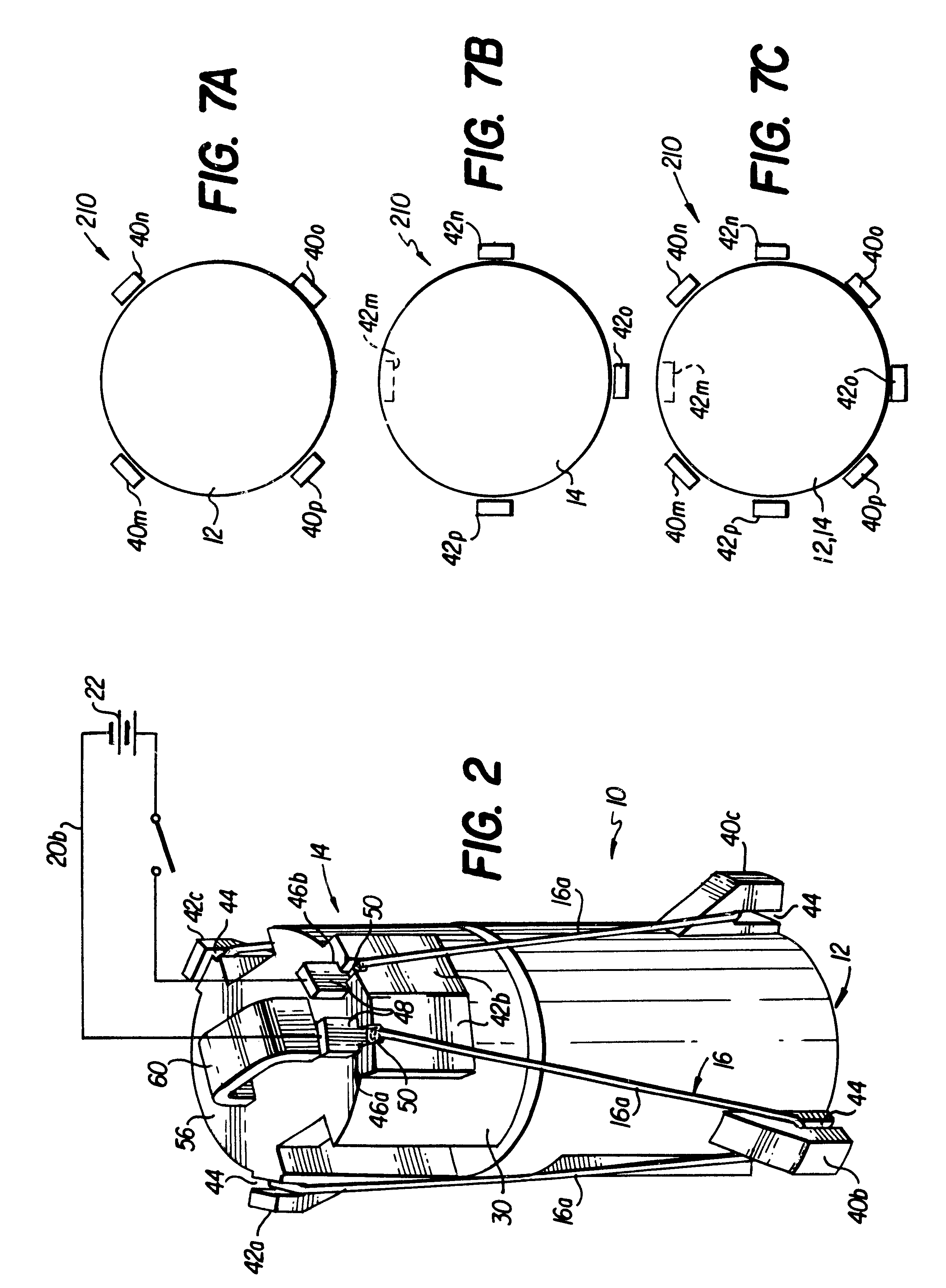
A first exemplary embodiment of a shape memory alloy wire actuator 10 of the invention is shown in FIGS. 1-5C and includes a first body member 12, a second body member 14 and a strand of shape memory alloy wire 16. The first body member 12 and the second body member 14 extend along a longitudinal axis L and are slidably engageable (FIGS. 3A-4B) with one another along the longitudinal axis L for linear, coaxial movement relative to one another. As the first and second body members 12 and 14 move coaxially relative to one another, the first and second body members 12 and 14 move between an extended or "open" state illustrated in FIGS. 2-3B and a contracted or "closed" state illustrated in FIGS. 4A-4B. In the extended state, as best shown in FIGS. 3A and 3B, the first and second body members 12 and 14 are resiliently biased apart from one another at a distance d. In the contracted state, as best shown in FIGS. 4A and 4B, the first and second body members 12 and 14 are displaced towards...


PUM


Abstract

A shape memory alloy wire actuator includes a first body member, a second body member and a strand of shape memory alloy wire. The first body member and the second body member extend along a longitudinal axis and are slidably engageable with one another along the longitudinal axis. The first and second body members move in a linear, coaxial fashion relative to one another between an extended state and a contracted state. The first and second body members are resiliently biased away from one another by a spring. The strand of shape memory alloy wire interconnects the first and second body members in a serpentine manner. When the shape memory alloy wire is energized, such as by an electrical current, the shape memory alloy wire shortens causing the first body member and the second body member to move from the extended state to the contracted state. When the shape memory alloy wire is de-energized, i.e., the electrical current is shut off, the shape memory alloy wire lengthens causing the first body member and the second body member move from the contracted state to the extended state under the force of the spring.

Description

The present invention relates to an actuator and more particularly to a shape memory alloy wire actuator.Shape memory alloys have been known and utilized for many years with various types of actuator devices. One example of such an actuator device is the hydraulic shape memory alloy actuator described in U.S. Pat. No. 4,945,727 to Whitehead et al. The hydraulic shape memory alloy actuator of Whitehead et al. includes a uniaxial shape memory alloy wire constructed of Nitinol and uses a pair of hydraulic cylinders in fluid communication with one another. Each cylinder contains a hydraulic piston. A first hydraulic piston is moved from a first position to a second position when the shape memory alloy wire, connected at one end of the first hydraulic piston and connected at the other end to a fixed point, changes from a martensitic state to an austenitic state upon heating. The second hydraulic piston responds to the movement of the first hydraulic piston by moving from a rest position ...

Claims


Application Information

Patent Timeline
IPC IPC(8): F03G7/06H01H61/00H01H61/01
CPCF03G7/065H01H61/0107
Inventor CORRIS, CHARLES JAMESDYESS, DANIEL KEITH
Owner ENERGY CONVERSION SYST HLDG
Why Eureka
Try Eureka