Plastic wheel assembly and mounting sleeve therefor

a technology of plastic wheels and mounting sleeves, which is applied in the direction of hubs, transportation and packaging, and refusing gathering, etc., can solve the problems of unduly complex prior art snap-on wheel mounting assemblies, unsuitable for shock loading and vibration, and difficult to remove such plastic wheels in order to replace or repair them, etc., to achieve compact size

Inactive Publication Date: 2002-04-23
GEO PLASTICS
View PDF11 Cites 51 Cited by
  • Summary
  • Abstract
  • Description
  • Claims
  • Application Information

AI Technical Summary

Benefits of technology

The wheel mounting sleeve of the present invention includes a sleeve body formed and dimensioned for mounting through a central wheel bearing bore and formed to be telescoped over an axle. The sleeve has at least one axle-engaging shoulder releasably retaining the sleeve on the axle and at least one wheel-engaging shoulder retaining the wheel on the sleeve. The improvement in the mounting sleeve of the present invention is comprised, briefly, of the sleeve body being formed with two resilient radially displaceable, cantilevered fingers. The fingers are cantilevered in opposite d

Problems solved by technology

Removal of such plastic wheels in order to replace or repair the same has been difficult because the hammered hubs require special tools for their removal or essentially must be destroyed to remove them from the axle.
Sometimes this process also damages the axles.
Prior art snap-on wheel-mounting assemblies, however, have been unduly complex, visually unappealing or not well suited to the shock loading and vibration which is commonly encountered in connection with wheeled refuse carts.
Moreover, the cost of prior art snap-on couplings has been undesirably high, as has their rate of failure.
This approach is based, in part, upon mating frictional engagement of the hub halves, but under the shock loading and high

Method used


Image

  • Plastic wheel assembly and mounting sleeve therefor
  • Plastic wheel assembly and mounting sleeve therefor
  • Plastic wheel assembly and mounting sleeve therefor

Examples


Embodiment Construction

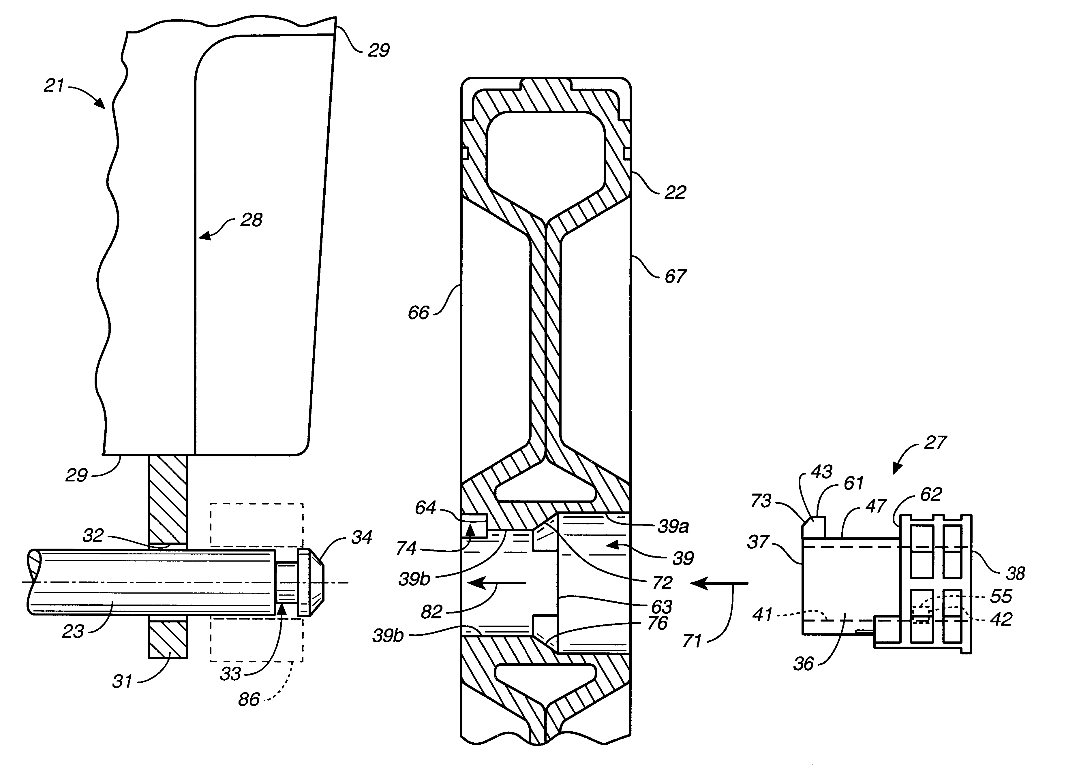
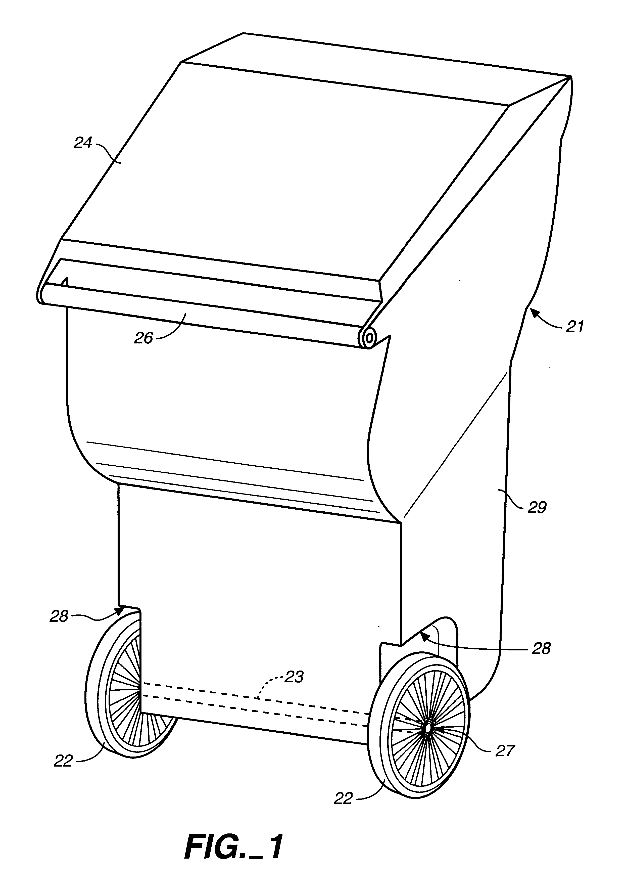
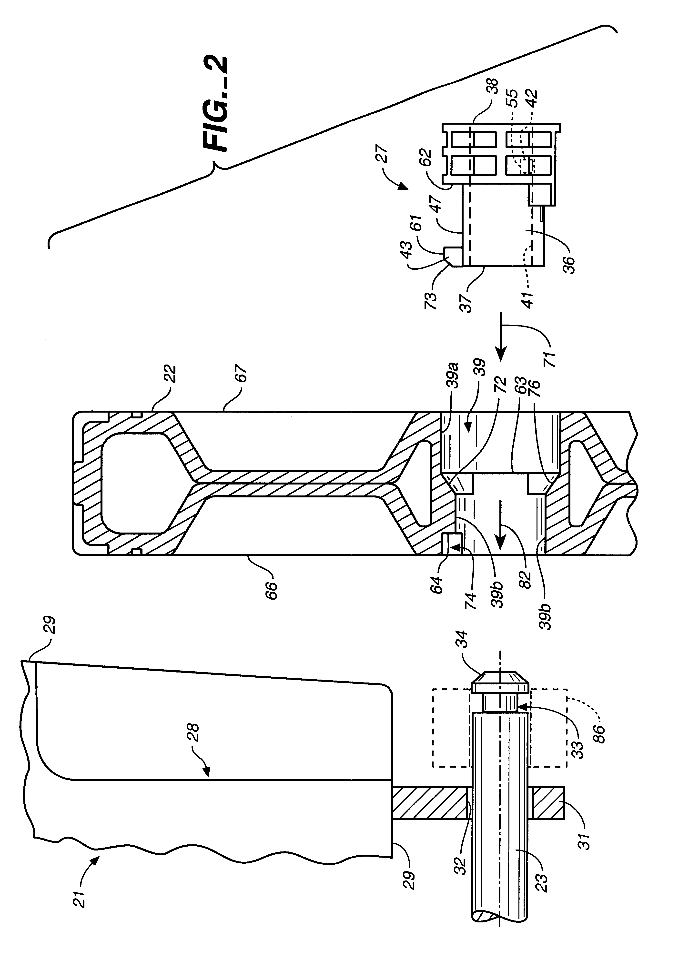
The wheel mounting sleeve and wheel assembly of the present invention can be used in connection with numerous wheeled devices. A typical, but not limiting, application is to employ the same in a wheeled refuse cart or container of the general type shown in FIG. 1. Thus, cart 21 includes a pair of wheels 22 mounted on an axle 23 to the lower end of the cart body 29. A hinged lid 24 optionally can be provided, and the cart can be tilted or tipped about the wheels using handle 26 so as to enable rolling of the cart for the transport of refuse, for example, between a location for filling the cart and a location for pickup by a refuse disposal company.

Wheels 22 are secured on axle 23 by a wheel mounting sleeve, generally designated 27. In the refuse cart illustrated, body 29 of the cart includes a wheel well or recess area 28 which receives wheels 22, in part to protect the wheels and in part as a cosmetic structure. Many carts, however, do not include wheel wells as illustrated.

In FIG. ...


PUM


Abstract

A plastic wheel (22) and wheel mounting sleeve (27, 27a, 27b, 27c) used to releasably secure the wheel (22) onto an axle (23). The wheel mounting sleeve (27) preferably includes two resilient, radially displaceable, axially extending, cantilevered fingers (46, 47) which are cantilevered from and extend axially in opposite directions on the sleeve (27). An axle-engaging shoulder (42) is provided on a radially inwardly extending lug (55) on one finger (46), while a wheel-engaging shoulder (43) is provided on a radially outwardly extending lug (61) on the other resilient finger (47). The respective shoulders (42, 43) cooperate with oppositely facing shoulders (58, 62) so as to releasably latch the sleeve (27) to the axle (23) and the wheel (22) to the sleeve (27). Assembly can be accomplished without any tools and a screwdriver can be used to disassemble the components. Alternative sleeves (27a, 27b, 27c) include an annular rib (101) which mates with an annular bore recess (102) to further limit relative movement between the sleeve (27a, 27b, 27c) and the wheel (22).

Description

The present invention relates, in general, to wheel assemblies and the manner of their mounting to and removal from an axle, and more particularly, relates to plastic wheel assemblies of the type used on refuse carts or the like and the manner in which they are mounted to and removed from the axle for such carts.The use of plastic wheels on a variety of products has dramatically increased in recent years. One area where such plastic wheels have been widely employed is on wheeled refuse or garbage carts or bins of the type commonly employed by homeowners for their trash. Typically, these carts are formed of an injection or rotationally molded plastic and have injection or blow molded plastic wheels which are mounted on the ends of a metal axle by a hub member. The wheel hub is hammered onto the end of the axle to hold the wheel in place. Removal of such plastic wheels in order to replace or repair the same has been difficult because the hammered hubs require special tools for their r...

Claims


Application Information

Patent Timeline
IPC IPC(8): B60B37/00B60B37/10B65F1/14
CPCB60B3/001B65F1/1473B60B37/10
Inventor MORRIS, MICHAEL A.
Owner GEO PLASTICS
Why Eureka
Try Eureka