Cable routing duct

a routing duct and cable technology, applied in the direction of cables, insulated conductors, instruments, etc., can solve the problems of long time-consuming, labor-intensive, and labor-intensive cable management, and achieve the effect of reducing labor intensity, reducing labor intensity, and reducing labor intensity

Inactive Publication Date: 2002-04-30
ERGOTRON
View PDF12 Cites 112 Cited by
  • Summary
  • Abstract
  • Description
  • Claims
  • Application Information

AI Technical Summary

Benefits of technology

According to one embodiment of the present invention, there is provided a one-piece cable routing duct, including a series of rectangular-shaped chambers having common back, top and bottom planar members. Each chamber includes an access panel which includes, at one end, a living hinge of co-injected plastic materials, and at the other end, a latch member. The latch member engages a hook member to provide a secured chamber. A three-sided wire or cable accommodation slot separates adjacent chambers and provides for branching of cables, or like-shaped elements, such as wire, tubes, optical fibers, etc., from the interior of the chambers for routing to external components or devices. Any number of chambers can be opened in succession or on an individual basis, as desired, to easily insert or remove cables without disturbing other branched cables which are contained by unopened chambers. The access panels, when opened for cable insertion, spring to an open position about the co-injected living hinges to allow passage of cables to the interior of the chambers without interference from the access panel, which is conveniently held out of the way by the spring memory of the co-injected material living hinges.
Another significant aspect and feature of the present invention is the incorporation of an angle between the planar back member and the planar bottom member for providing a positive locking method between planar members of the accessible chambers.

Problems solved by technology

Cable management has always been a time consuming, labor intensive task, usually requiring dexterity and patience, and extensive manual time-consuming labor.

Method used


Image

  • Cable routing duct
  • Cable routing duct
  • Cable routing duct

Examples


Embodiment Construction

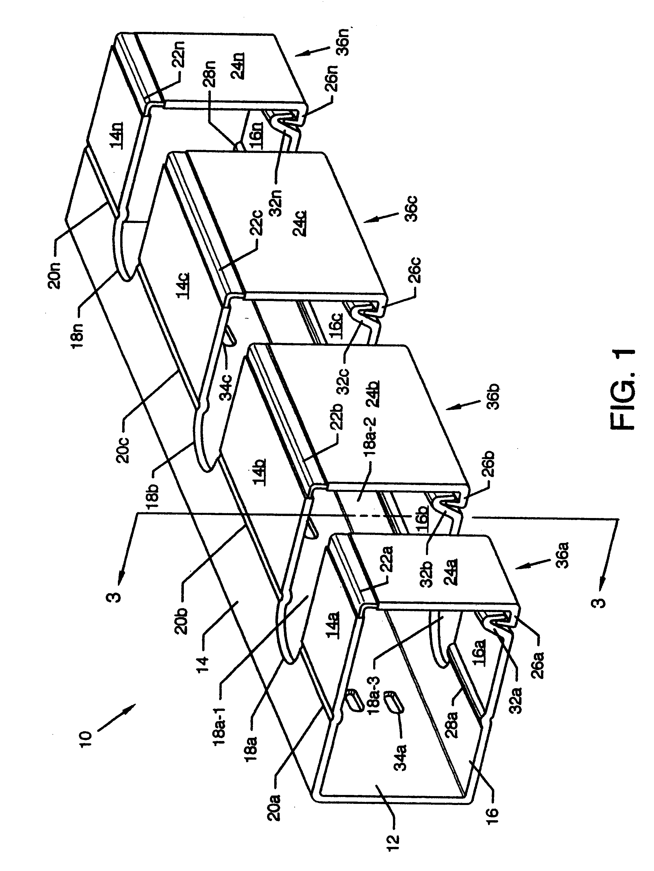
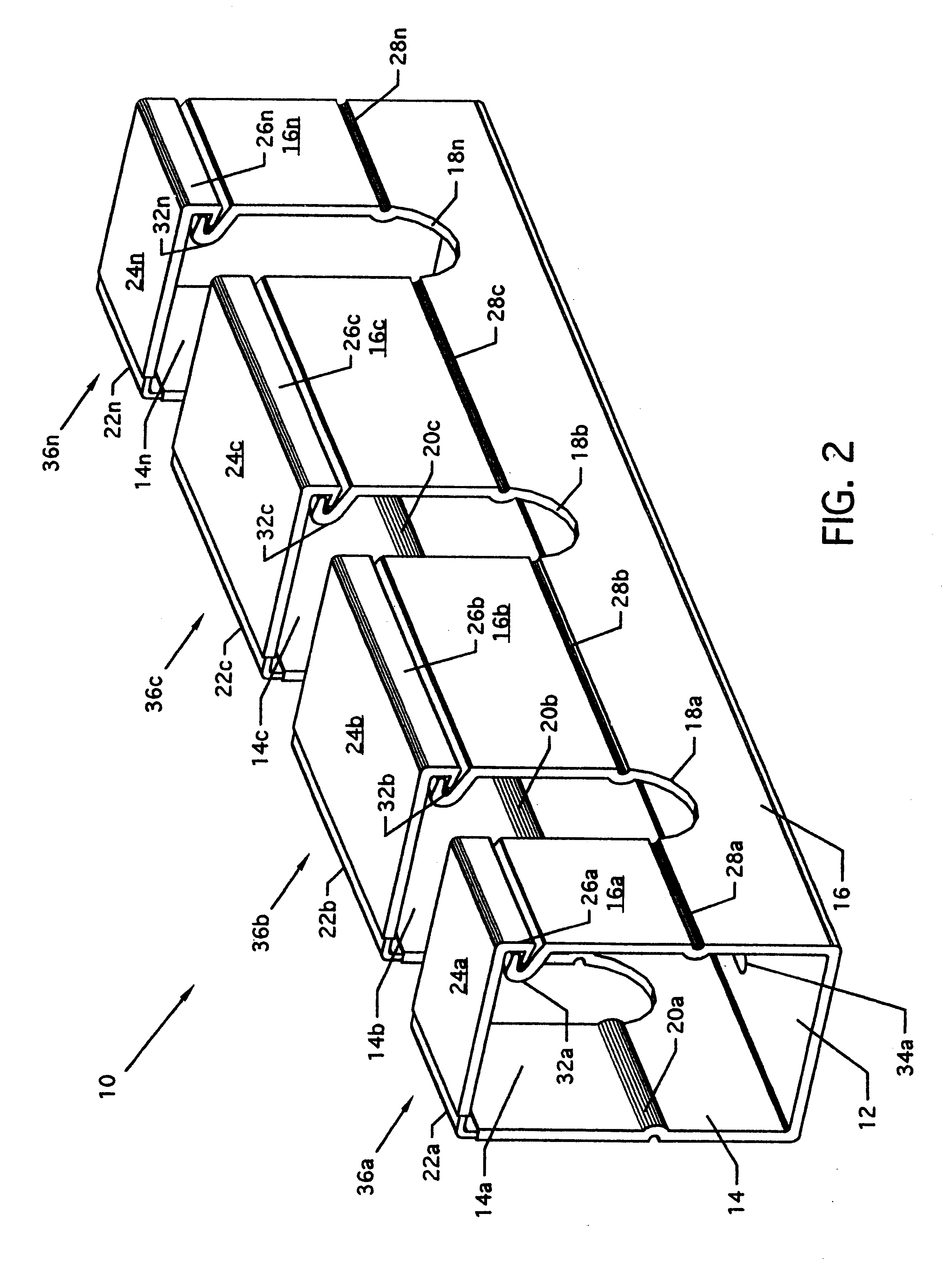
FIG. 4 illustrates the cable duct of FIG. 3 having a plurality of cables 38a-38e residing in the chamber 36a (see FIG. 5) of the cable routing duct 10 and extending into chamber 36b, where all numerals correspond to those elements previously or otherwise described. Cable 38d is illustrated as exiting the interior area of the cable routing duct 10 from the upper horizontally aligned wire portion 18a-1 of the wire accommodation slot 18a. Cable 38e exits the interior area of the cable routing duct 10 from the lower horizontally aligned wire portion 18b-3 of the wire accommodation slot 18b. Access panel 24b is rotated about the living hinge 22b, as illustrated by arrow 40, to allow access to the chamber 36b for placement of cable 38f into the chamber 36b subsequent to manual disengagement of latch member 26b from hook member 32b. The co-injected materials of the living hinges 22a-22n exhibit memory to keep the access panels 24a-24n positioned away from the openings to the chambers 36a-3...


PUM


Abstract

Cable routing duct for orderly carriage of and branching off or routing of wires, cables, fiber optics, tubular elements and the like, having a series of accessible chambers interrupted by wire accommodation slots. Access panels pivot about living hinges fashioned of co-injected plastic materials to allow access to the chambers.

Description

1. Field of the InventionThe present invention is for a cable routing duct, and more particularly, pertains to a cable routing duct having a series of accessible chambers and adjacent accommodation slots for cables or like-shaped elements.2. Description of the Prior ArtRouting of cables is like unraveling fishing line or uncoiling a rattlesnake. Cable management has always been a time consuming, labor intensive task, usually requiring dexterity and patience, and extensive manual time-consuming labor.The present invention overcomes the disadvantages of the prior art by providing a cable routing duct which can be easily installed with simple tools, such as a drill and screwdriver, and with simple hardware, such as screws or nuts and bolts, and which can easily be configured by a simple cutting device, such as a saw or shears.The general purpose of the present invention is to provide a cable routing duct.According to one embodiment of the present invention, there is provided a one-piec...

Claims


Application Information

Patent Timeline
Patent Type & Authority Patents(United States)
IPC IPC(8): F16L3/26F16L3/00H02G3/04
CPCF16L3/26H02G3/045G02B6/4459H02G3/0431
Inventor THEIS, JOHN W.SWEERE, HARRY C.
Owner ERGOTRON
Why Eureka
Try Eureka