Line testing in a telecommunications network

a telecommunications network and line testing technology, applied in the field of line testing in a telecommunications network, can solve the problems of not knowing whether the pair of cables is connected, difficult or even impossible for the engineer to discover the identity of the pair of copper wires, and not being able to use the test equipmen

Inactive Publication Date: 2002-05-07
BRITISH TELECOMM PLC
View PDF15 Cites 16 Cited by
  • Summary
  • Abstract
  • Description
  • Claims
  • Application Information

AI Technical Summary

Problems solved by technology

This causes two problems.
Firstly, when an engineer wishes to check the identity of a pair of copper cables, he may not know whether the pair of cables is connected to a local switch which has such test equipment.
Secondly, when an engineer wishes to check the identity of a pair of copper cables which are connected to a local switch which does not have such test equipment, it may be difficult or even impossible for the engineer to discover the identity of the pair of copper wires;
However, if the engineer is unable to dial in on one of the terminating lines of the switch and he does not know the full code number of the test equipment, he is faced with the problem of not being able to use the test equipment.

Method used


Image

  • Line testing in a telecommunications network
  • Line testing in a telecommunications network
  • Line testing in a telecommunications network

Examples


Embodiment Construction

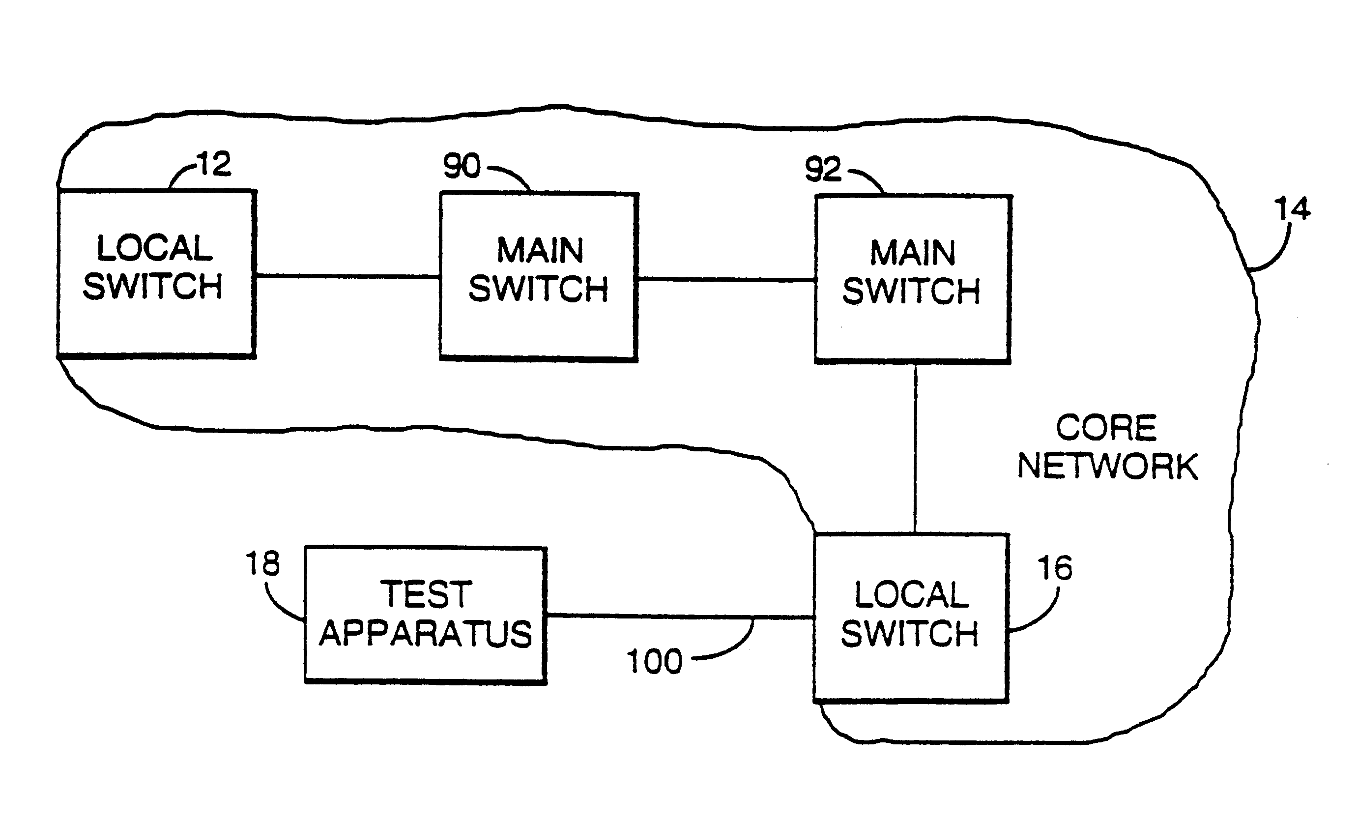
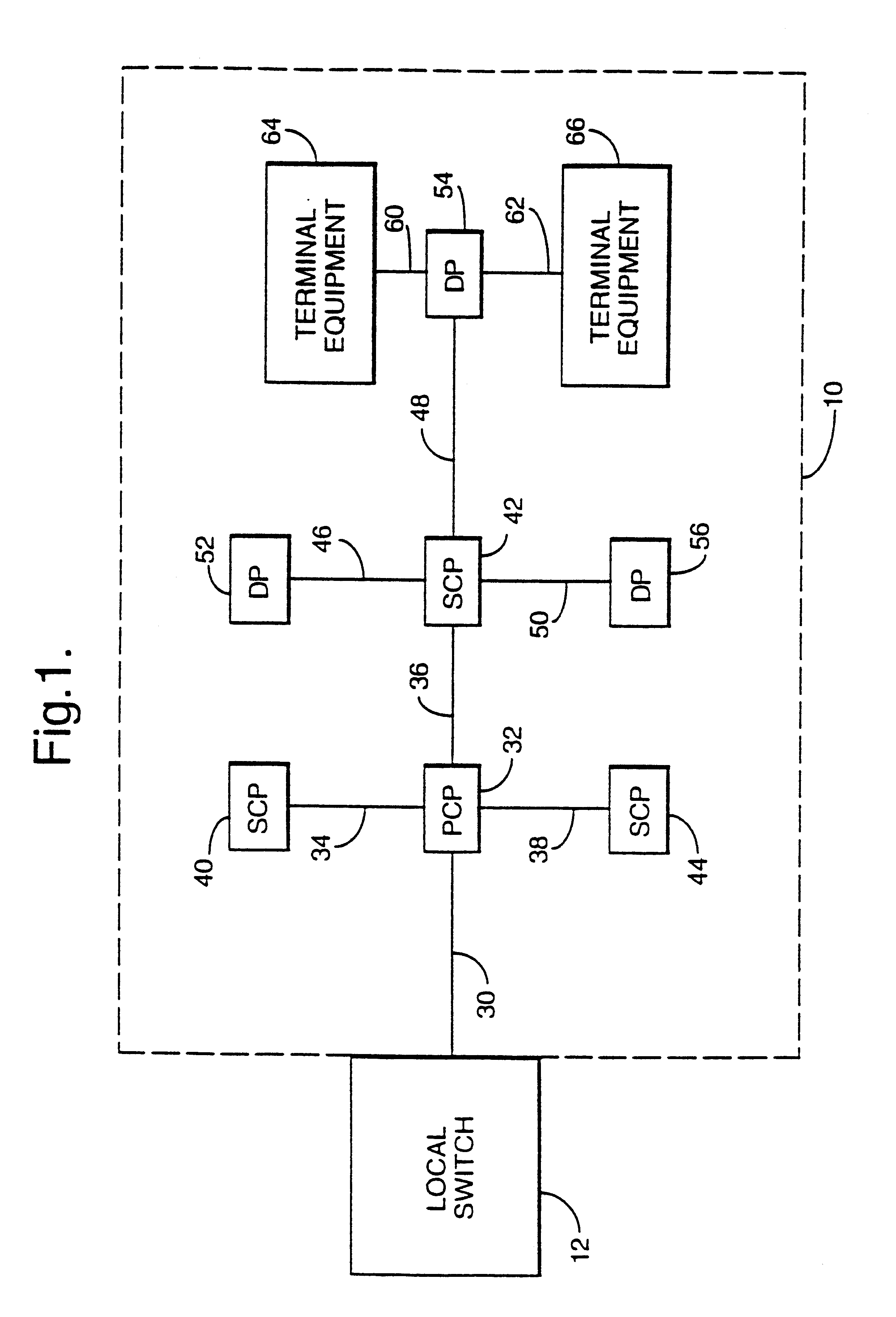
Referring now to FIG. 1, the local switch 12 is connected to the terminating lines of the public telecommunications network for the area which it serves. Typically a local switch is connected to several thousand terminating lines. Each terminating line passes through several junctions before reaching its respective terminal equipment.

Each terminating line is formed from a pair of copper wires. The copper wires leave the local switch 12 in the form of one or more cables. One of these cables is shown in FIG. 1 and indicated by reference numeral 30. The far end of cable 30 from switch 12 is connected to a primary cross-connect point (PCP) 32 which may be housed in a street cabinet or underground junction box. From the primary cross-connect point 32, the terminating lines branch out as cables in several directions. For reasons of simplicity, in FIG. 1 there are shown only three cables 34, 36 and 38 leaving the primary cross-connect point 32. The far ends of cables 34, 36 and 38 from the...


PUM


Abstract

A centralized test apparatus is provided for a telecommunications network which includes local switches and a core network. Each local switch is connected through terminating lines to terminating equipment such as telephone handsets. The test apparatus enables a field engineer to obtain the identity of a terminating line from one of the local switches. When a field engineer dials the number of the test apparatus, the test apparatus retrieves the calling line identity on answering the call. It then transmits the calling line identity in speech form back to the calling line. After transmitting the calling line identity, the test apparatus offers a menu of further services which comprise a ring back service and the provision of a test tone on a specified telephone line.

Description

1. Field of the InventionThis invention relates to a method of, and an apparatus for, line testing in a telecommunications network.2. Related ArtA conventional public telecommunications network comprises a relatively small number of interconnected main switches and a much larger number of local switches, each of which is connected to one or two main switches. The local switches are connected to the terminating lines of the network and the far ends of these lines are connected to terminal equipment, such as telephone instruments 10 located in customers' premises. The network formed from the main switches and local switches is known as the core network while the network formed from the terminating lines is known variously as the access network or local loop. In this specification, it will be referred to as the access network. In the access- network, each terminating line is formed from a pair of copper wires and, typically, between the local switch and terminal equipment, each termina...

Claims


Application Information

Patent Timeline
Patent Type & Authority Patents(United States)
IPC IPC(8): H04M3/28H04M3/30H04M3/22H04Q1/30H04Q3/72H04M7/00H04M3/487H04Q1/446
CPCH04M3/229H04M3/30H04Q3/72H04M7/00H04Q1/446H04M3/487
Inventor BROOKS, ALVINWARD, FRANK GRAHAMLEE, STEPHEN F
Owner BRITISH TELECOMM PLC
Why Eureka
Try Eureka