Method for continuous casting of steel

a technology of continuous casting and steel, applied in the field of continuous casting of steel, can solve the problems of inability to practice a thin slab casting technique, inability to increase the thickness of a material used in a submerged entry nozzle, and easy melting loss of the nozzl

Inactive Publication Date: 2002-05-14
SUMITOMO METAL IND LTD
View PDF15 Cites 80 Cited by
  • Summary
  • Abstract
  • Description
  • Claims
  • Application Information

AI Technical Summary

Problems solved by technology

It is difficult to practice a technique for casting a thin slab with a thickness of 40-80 mm by means of a generally used mold in which the inlet and outlet are of the same thickness.
The thickness of a material used in a submerged entry nozzle cannot be increased, and the nozzle is susceptible to melting loss.
Thus, in the course of casting, an accident in which the nozzle breaks and casting cannot be carried out may occur.
However, when casting speed increases, the amount of molten slag which flows into a gap between the inner wall of a mold and a solidified shell decreases.
When the inflow amount of molten slag decreases and the thickness of molten slag decreases, a solidified shell tends to bind to the inner wall of a mold, due to insufficient lubrication.
However, when mold powder with a lower solidification temperature and viscosity is employed, the thickness of molten slag tends to be uneven.
Thus, a solidified shell in a mold is not cooled evenly, and longitudinal cracks tend to form on the surface of a slab.
Incidentally, it is well known that a molten steel of a peritectic steel is solidified unevenly, and thus longitu

Method used


Image

  • Method for continuous casting of steel
  • Method for continuous casting of steel

Examples


Embodiment Construction

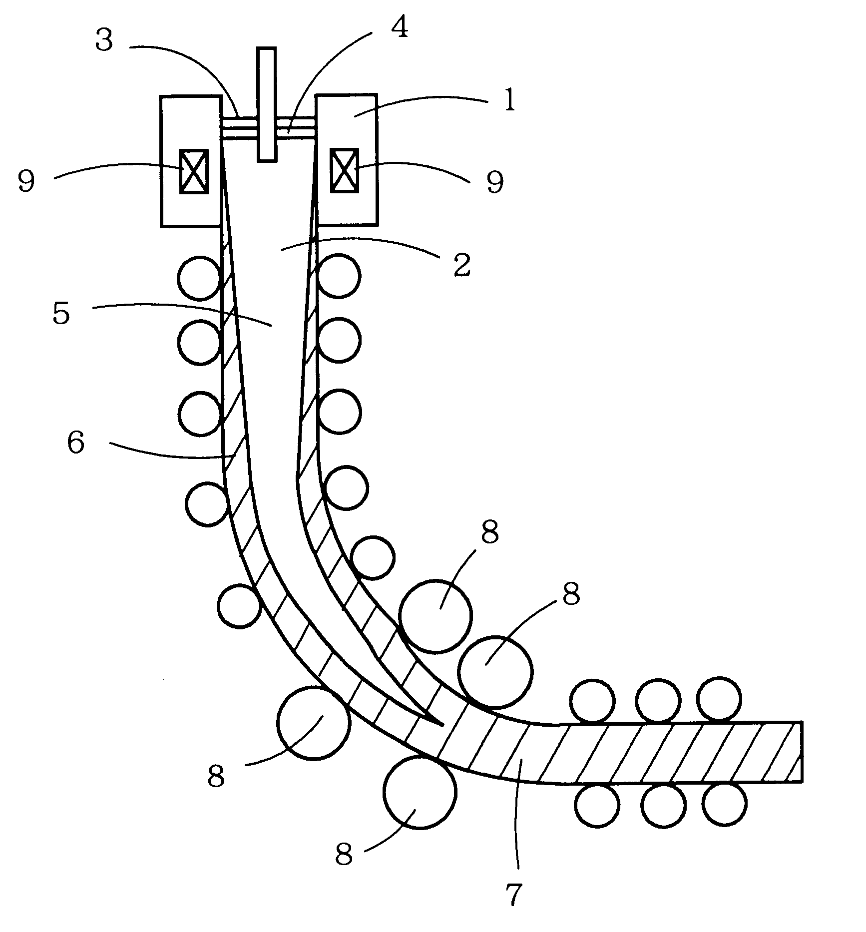
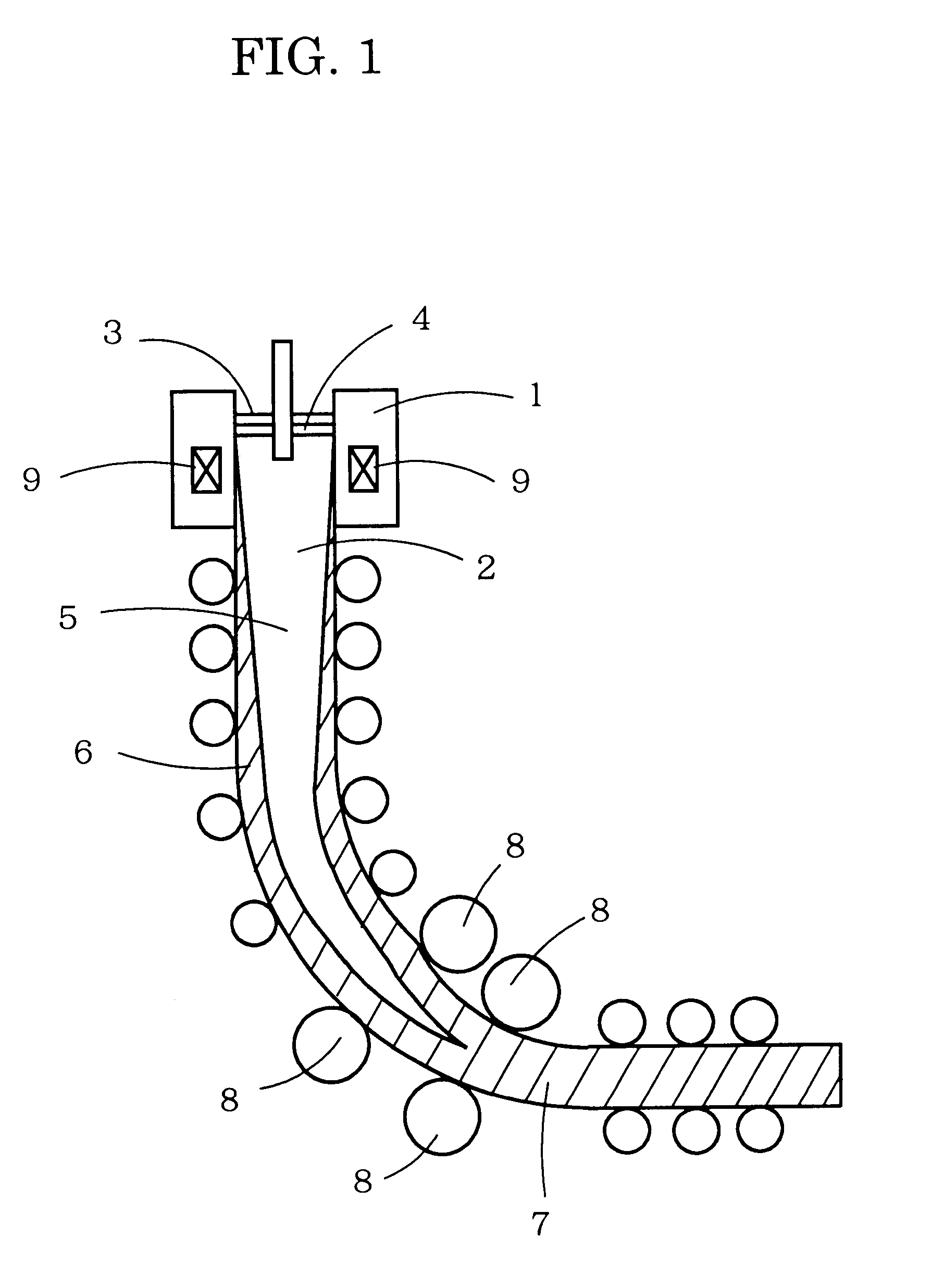
In an apparatus of the constitution shown in FIG. 1, casting tests were performed by use of a vertical-bending-type continuous casting apparatus which comprises a slab reduction apparatus and an electromagnetic brake applying an electromagnetic force on molten steel flow from a submerged entry nozzle in a mold. The length of a vertical portion was 1.5 m, and the radius of a curved portion was 3.5 m.

Magnetic field intensity of the electromagnetic brake (molten steel flow regulation apparatus) was 0.3-0.5 tesla (T). The term "magnetic field intensity" refers to a magnetic field intensity at the position which is the coil center of the electromagnetic brake and the center in a thickness direction of the mold. The slab reduction apparatus was provided at the position 2.8 m away from the meniscus of molten steel.

Hypo-peritectic steel shown in Table 1 was cast into a slab with a thickness of 90 mm and a width of 1,200 mm by use of a mold whose inlet and outlet are of the same thickness. I...


PUM

PropertyMeasurementUnit
Temperatureaaaaaaaaaa
Lengthaaaaaaaaaa

Abstract

A method of continuous casting of a steel employs a mold power having a viscosity of 0.5-1.5 poise at 1,300° C. and a solidification temperature of 1,190-1,270° C., in which the mass ratio of CaO to SiO2 is 1.2-1.9, and casting is carried out under the following conditions: casting speed is 2.5-10 m/minute; mold oscillation stroke is 4-15 mm; and specific cooling intensity in secondary cooling of a slab is 1.0-5.0 liter/kg-steel.

Description

This application claims priority under 35 U.S.C. .sctn..sctn.119 and / or 365 to JP 11-166082 filed in Japan on Jun. 11, 1999, the entire content of which is herein incorporated by reference.1. Technical FieldThe present invention relates to a method for continuous casting of a steel such as a peritectic steel at high speed. The method enables a steady operation due to a prevention of a break-out and an periodic fluctuation of molten steel level during the casting, and can produce a slab having excellent surface quality; i.e., a slab having no longitudinal cracks on the surface.2. Background ArtIn a method for continuous casting of a steel slab, in view of slab quality and productivity, generally, a slab with a thickness of 150-300 mm is cast at a speed of about 1-2 m / minute. In recent years, in consideration of reduction in construction cost of related equipment and the number of operators, casting of a slab with a thickness and shape similar to those of a product has been attempted....

Claims


Application Information

Patent Timeline
IPC IPC(8): B22D11/11B22D11/111B22D11/128B22D11/14B22D11/051B22D11/10B22D11/108B22D11/124
CPCB22D11/111B22D11/14B22D11/128
Inventor KAWAMOTO, MASAYUKIHANAO, MASAHITOKIKUCHI, HIROHISAMURAKAMI, TOSHIHIKOOKA, MASAHIKO
Owner SUMITOMO METAL IND LTD
Why Eureka
Try Eureka