Subsea wellhead system and method for drilling shallow water flow formations

a wellhead system and shallow water technology, applied in the field of subsea drilling, can solve the problems of time-consuming and expensive procedures, add to operating difficulties, and high cost of ball valves

a wellhead system and shallow water technology, applied in the field of subsea drilling, can solve the problems of time-consuming and expensive procedures, add to operating difficulties, and high cost of ball valves

US6386291B1Inactive Publication Date: 2002-05-14FMC CORP

Image

  • Subsea wellhead system and method for drilling shallow water flow formations
  • Subsea wellhead system and method for drilling shallow water flow formations
  • Subsea wellhead system and method for drilling shallow water flow formations

Examples


Embodiment Construction

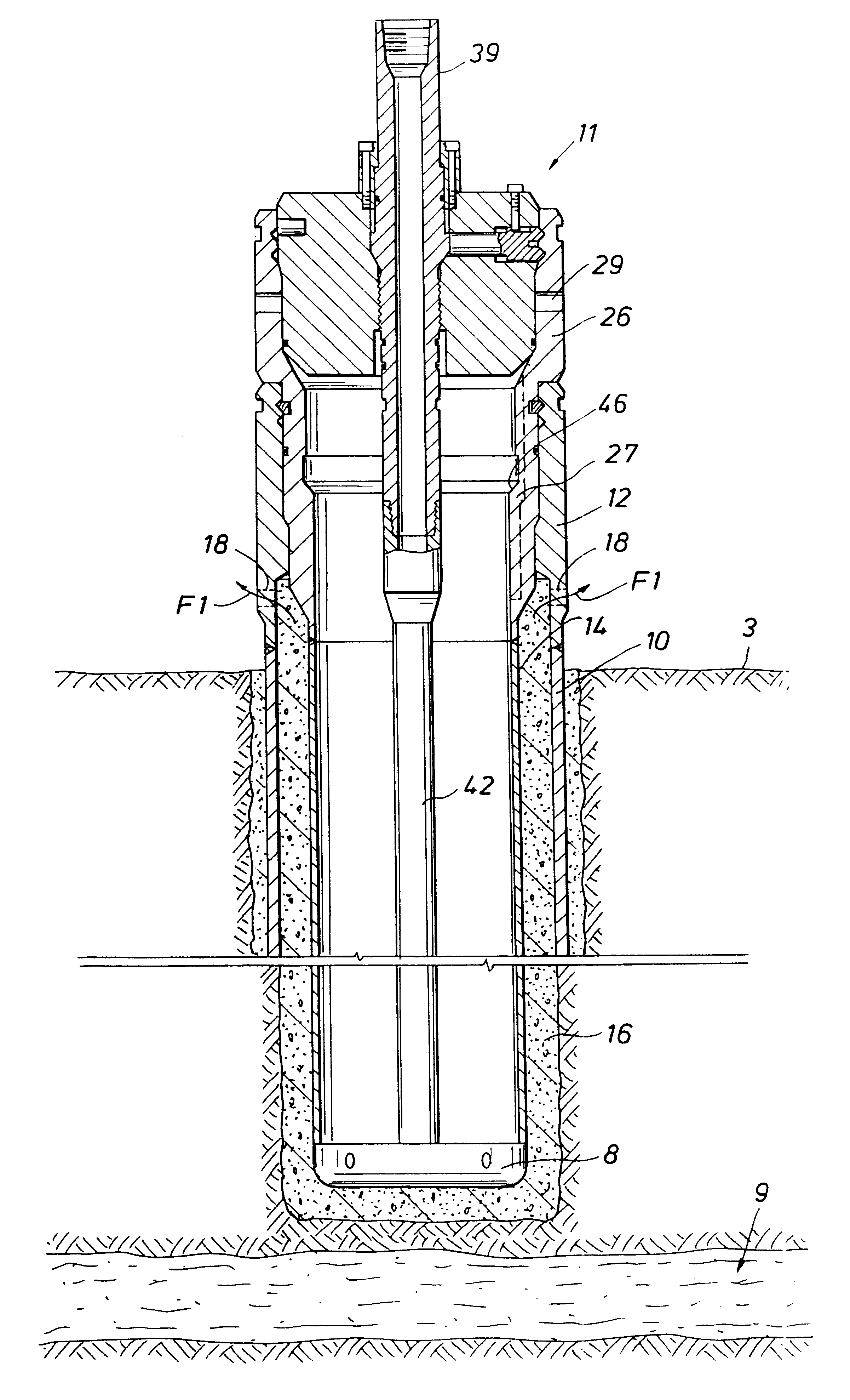
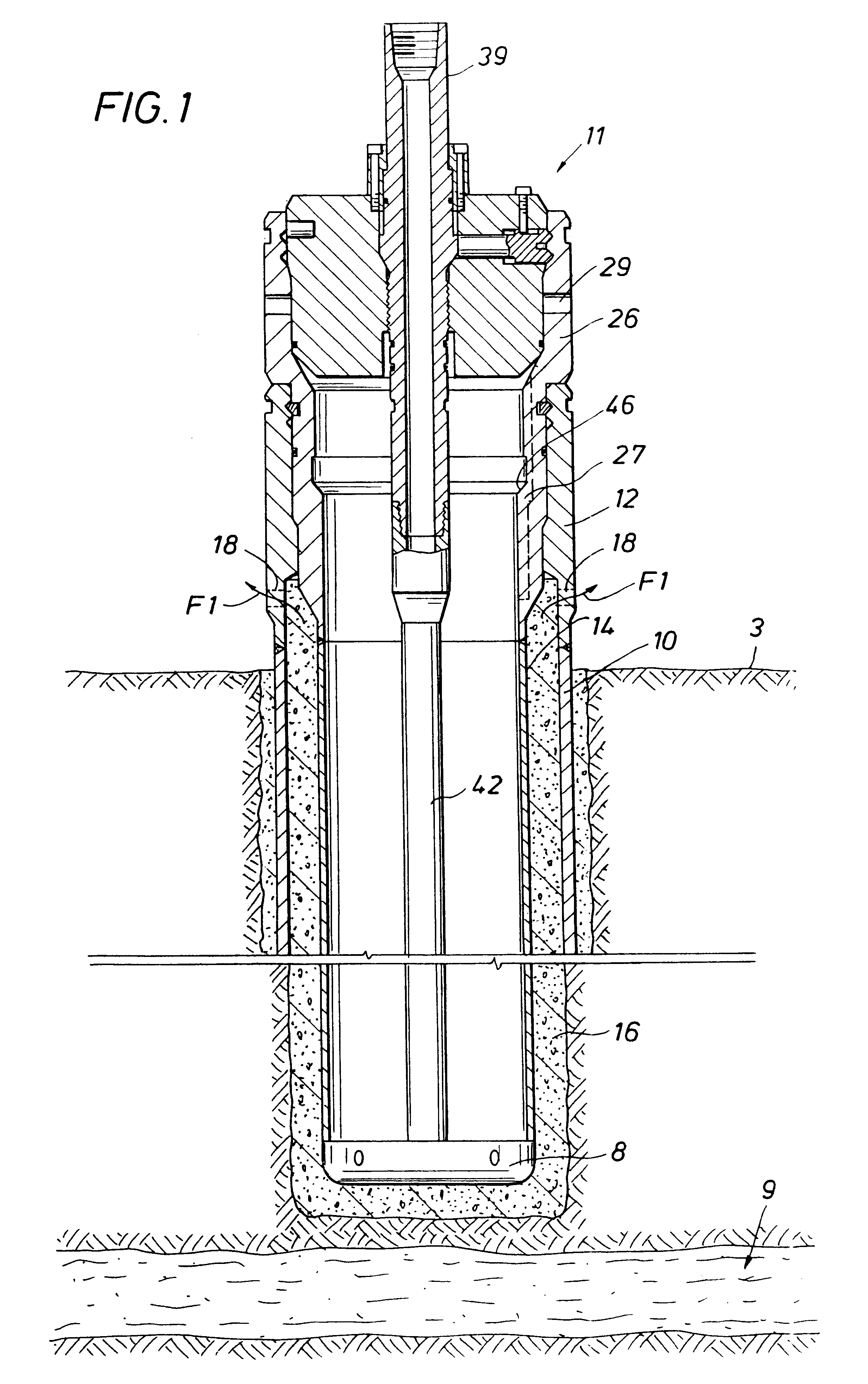
FIG. 1 illustrates a subsea wellhead assembly with a 36" wellhead assembly 12 secured to the top of a 36" conductor pipe 10 which is positioned within a hole in the seal floor 3 and formed and secured in the hole in a conventional manner. A borehole has been reamed through the 36" conductor pipe 10 large enough to accept a 26" pipe 14. Such borehole terminates (as shown diagrammatically) above the known depth of shallow water flow zone 9.

A running and cementing tool 11 conveyed by a drill pipe string from a service vessel (not shown) is releasably secured to the 26" wellhead housing 26 which carries the 26" pipe 14 into the borehole. The drill pipe suing is connected to tool 11 at threaded coupling 39 (not shown). A cementing shoe 8 communicates with cementing apparatus at the surface vessel via the drill pipe string. A lower portion 42 of a conduit which connects from the drill sting is carried by running and cementing tool 11. Cement 16 is forced to flow at the bottom of the hole ...


PUM


Abstract

A shallow water flow subsea drilling system is disclosed. A wellhead system is provided with a 36'' conductor pipe in which a 26'' casing and 26'' wellhead housing are landed. The 26'' casing extends to a depth above a shallow water flow zone. A borehole through the shallow water flow zone is sized to accept a 20'' casing to the top of which is secured an 18¾'' wellhead housing. An annulus between the 26'' and 18¾'' housings communicates with cement returns from the 20'' casing. Flow-by holes in the 26'' wellhead housing are sealed with a retrievable seal assembly and actuating mechanism run on the same running tool with the 20'' casing and 18¾'' wellhead housing. A hydraulic feedback mechanism is provided to sense at the service vessel whether or not the seal assembly has been correctly positioned in the annulus. The seal assembly is pressure tested in the same trip while in its pack-off condition and can be retrieved with a second running tool trip.

Description

1. Field of the InventionThis invention relates generally to the field of subsea drilling and in particular to a wellhead arrangement for use in drilling through shallow formations beneath the sea bed which are water bearing and under pressure.2. Description of the Prior ArtA common subsea drilling technique involves first providing a large diameter hole and installing a conductor casing typically 36" in diameter through the mud base of the seabed. Typically a low pressure or external wellhead housing is secured to the top of the conductor casing. Next, the well is bored through shallow earth formations to accept 26" casing. The 26" casing is installed in the hole with an internal or high pressure wellhead housing connected at its top and extends upwardly from the 26" casing. The 26" casing is cemented into the borehole through the use of a drill pipe conveyed cementing tool to the bottom of the hole. Cement is applied in the annulus between the 26" casing and the borehole and up th...

Claims


Application Information

Patent Timeline
14 May 2002
Publication
US6386291B1
IPC
E21B33/03; E21B34/04; E21B34/00; E21B33/038; E21B33/05; E21B33/035; E21B33/043
CPC
E21B33/0355; E21B33/038; E21B34/04; E21B33/05; E21B33/043
Inventors
SHORT, DAVID E.; VALKA, WILLIAM A.