Cleaning apparatus
a technology of cleaning apparatus and cleaning liquid, which is applied in the direction of combustible gas purification/modification, cleaning using liquids, and cleaning processes, etc., can solve the problems of large manufacturing cost of the apparatus, large apparatus, and relatively expensive nozzles that are resistant to high pressure cleaning liquids
- Summary
- Abstract
- Description
- Claims
- Application Information
AI Technical Summary
Benefits of technology
Problems solved by technology
Method used
Image

Examples
examples 7 to 12
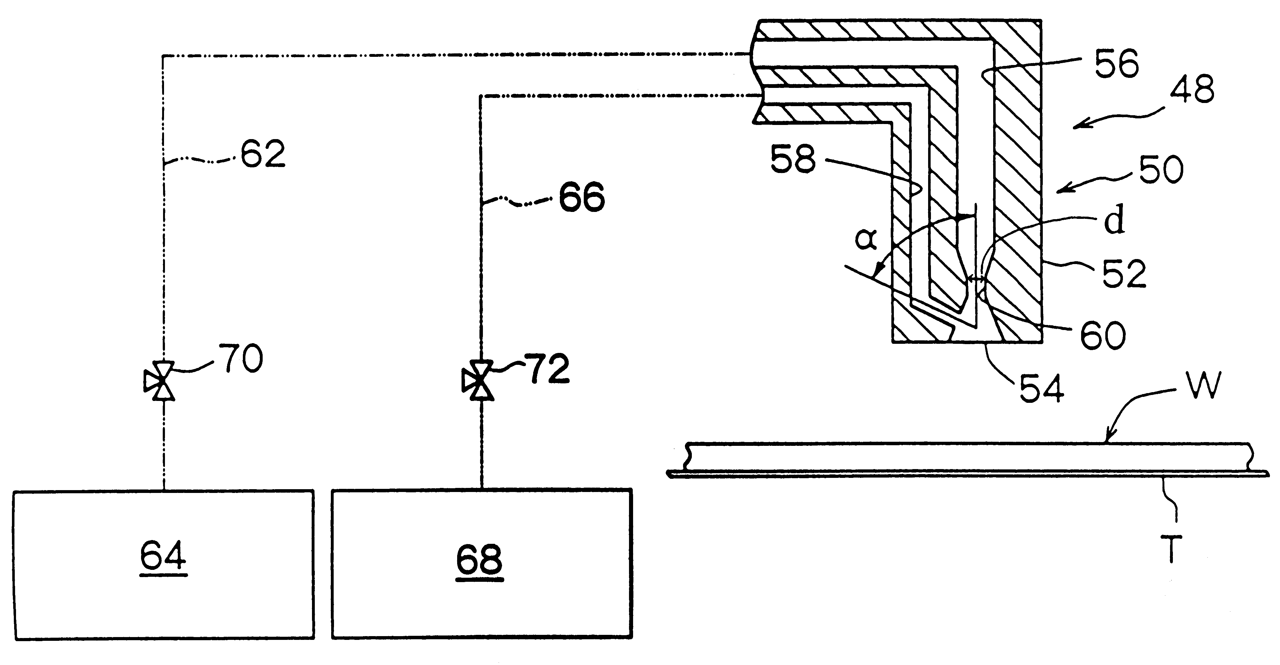
The cleaning rate was determined in the same manner as in Examples 1 to 6, except that the internal diameter of the constriction in the compressed gas path of the nozzle means was 1.1 mm. The results are shown in Table 2.
examples 13 to 18
The cleaning rate was determined in the same manner as in Examples 1 to 6, except that the internal diameter of the constriction in the compressed gas path of the nozzle means was 1.4 mm. The results are shown in Table 3.
examples 19 to 24
The cleaning rate was determined in the same manner as in Examples 1 to 6, except that the internal diameter of the constriction in the compressed gas path of the nozzle means was 1.8 mm. The results are shown in Table 4.
PUM
| Property | Measurement | Unit |
|---|---|---|
| pressure | aaaaa | aaaaa |
| internal diameter | aaaaa | aaaaa |
| internal diameter | aaaaa | aaaaa |
Abstract
Description
Claims
Application Information
 - R&D
- Intellectual Property
- Life Sciences
- Materials
- Tech Scout
- Unparalleled Data Quality
- Higher Quality Content
- 60% Fewer Hallucinations
Browse by: Latest US Patents, China's latest patents, Technical Efficacy Thesaurus, Application Domain, Technology Topic, Popular Technical Reports.
© 2025 PatSnap. All rights reserved.Legal|Privacy policy|Modern Slavery Act Transparency Statement|Sitemap|About US| Contact US: help@patsnap.com