Water production method

Inactive Publication Date: 2015-11-12
TORAY IND INC
View PDF0 Cites 2 Cited by
  • Summary
  • Abstract
  • Description
  • Claims
  • Application Information

AI Technical Summary

Benefits of technology

The present invention relates to a method for improving the removal of coagulation flocks from a separation membrane in a filtration process. The method involves cleaning the membrane with a first cleaning water having a higher pH than the water to be filtrated. It is found that using cleaning water with a pH higher than the water to be filtrated can improve the pressure difference across the membrane. However, it is also found that using cleaning water with a pH higher than the water to be filtrated may decrease the removal rate of the component to be removed. To address this, a second back washing substep is conducted using a filtrated water having a pH not significantly different from the water to be filtrated. This helps to maintain the removal rate of the component to be removed while reducing the pH of the water to be filtrated. Additionally, the pH adjuster can be introduced in the separated liquid to further stabilize the operation of the separation membrane module.

Problems solved by technology

When the techniques disclosed by Patent Documents 1 and 2 are applied for the purpose of suppressing the increase in the amount of the coagulant, safe operation may become difficult by the rapid increase in the transmembrane pressure difference.
In the meanwhile, the back wash conducted by using the high pH cleaning water disclosed in Patent Documents 3 and 4 may invite problems such as increase in the cost of chemicals required for the back wash and requirement of a large amount of water for neutralizing the membrane.
This results in the problem of reduced removal performance.

Method used


Image

  • Water production method
  • Water production method
  • Water production method

Examples


example 1

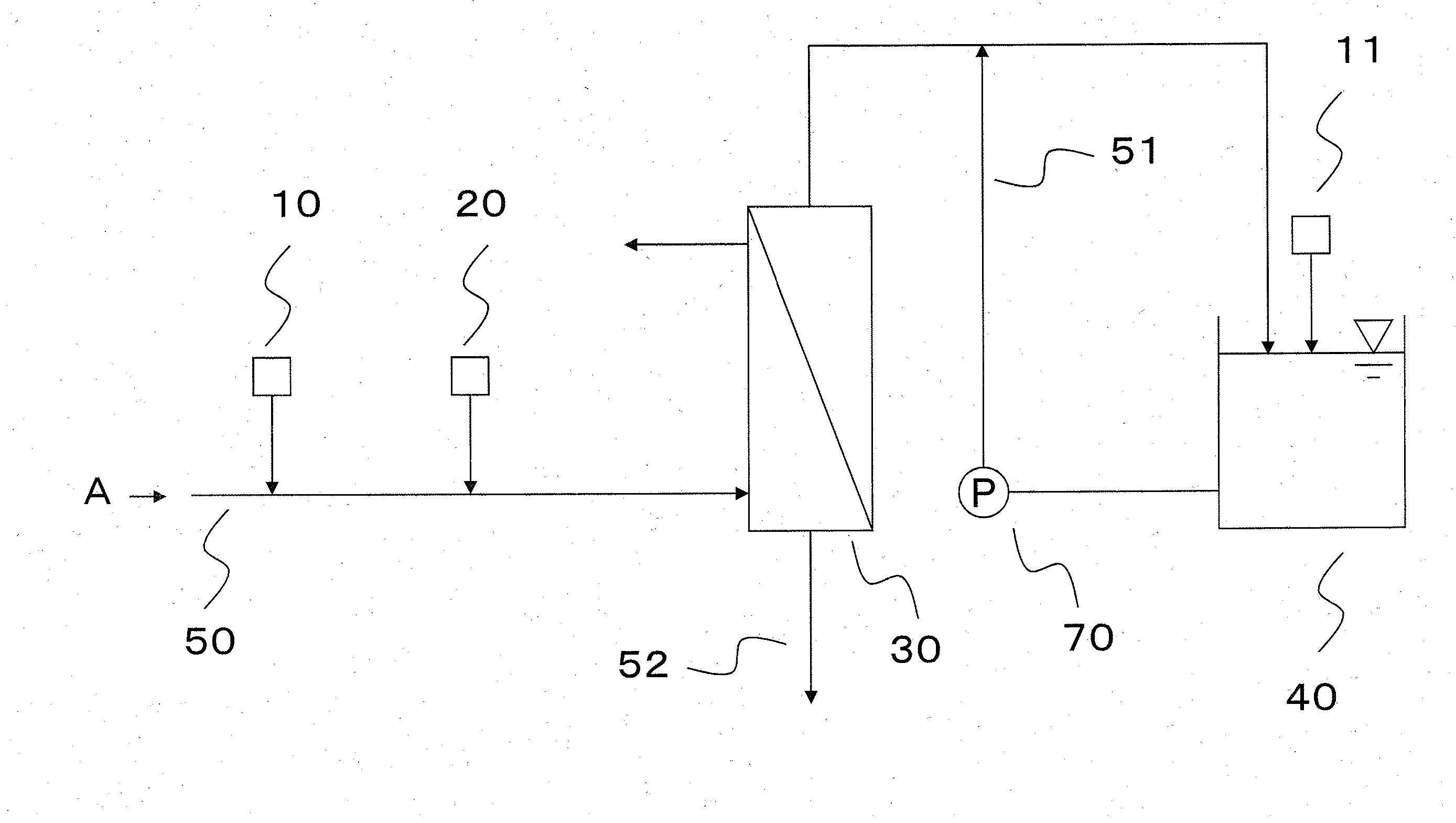
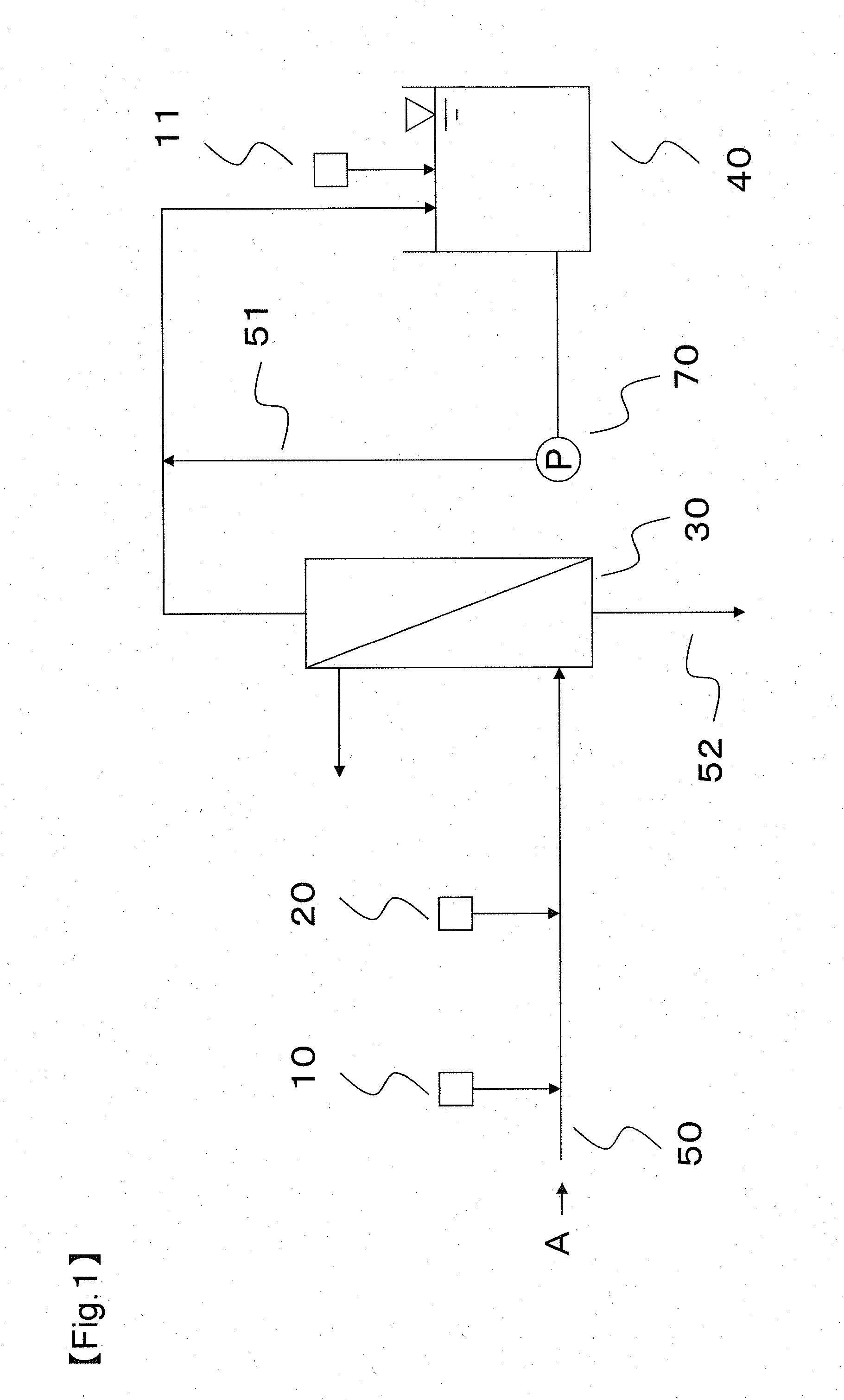
[0068]The water production was conducted by using the apparatus shown in the flow chart of FIG. 1, and the water to be treated was sewage water which had undergone the secondary treatment. In the first pH adjustment apparatus 10, the pretreated water was adjusted to pH 5.0 by using sulfuric acid, and in the cationic coagulant introducing apparatus 20, polyaluminum chloride (hereinafter referred to as PAC) was used for the cationic coagulant and PAC was added to the water supply line 50 so that PAC concentration in the pretreated water was 50 mg / L. PAC was mixed by using a line mixer. The pretreated water (the water to be filtrated) was filtrated through a membrane in the separation membrane module 30, and the filtrated water was stored in the filtrated water tank 40 that had been provided in the downstream of the separation membrane module 30. The filtrated water tank 40 had a second pH adjustment apparatus 11, and caustic soda was introduced so that the filtrated water tank 40 was ...

example 2

[0073]Continuous operation was conducted by using the conditions equivalent with the method described in Example 1 except that the pH of the cleaning water was adjusted to a pH of 7.0. The ΔA value and its increase rate and the ΔB value, the pH in the interior of the separation membrane module after the step of water supplying, the and removal rate of the component to be removed were measured, and the results are shown in Table 1.

example 3

[0074]Continuous operation was conducted by using the conditions equivalent with the method described in Example 1 except that the pH of the cleaning water was adjusted to a pH of 8.0. The ΔA value and its increase rate and the ΔB value, the pH in the interior of the separation membrane module after the step of water supplying, the and removal rate of the component to be removed were measured, and the results are shown in Table 1.


PUM


Abstract

Provided is a process for producing water including generating a water to be filtrated wherein a water to be treated is treated to generate a water to be filtrated; filtration wherein the water to be filtrated is filtrated through a separation membrane module having a separation membrane to generate a filtrated water; back washing wherein the substance to be removed by filtration which has blocked the separation membrane in the step of filtration is washed away by using a cleaning water; and drainage wherein cleaning drainage generated in the step of back washing is drained; wherein the step of generating the water to be filtrated has a coagulation substep of adding a first pH adjuster and a cationic coagulant to coagulate the substance to be removed by filtration in the water to be treated to thereby generate the pretreated water; the water to be filtrated used in the step of filtration satisfies the following expression (i); and the step of back washing has at least first back washing substep wherein the separation membrane is back-washed by the cleaning water satisfying the following expressions (ii) and (iii):4.0≦pH of the water to be filtrated≦6.5  (i)pH of the cleaning water≦9.0  (ii)pH of the cleaning water−pH of the water to be filtrated≧1.0  (iii).

Description

CROSS REFERENCE TO RELATED APPLICATIONS[0001]This is the U.S. National Phase application of PCT International Application No. PCT / JP2013 / 073318, filed Aug. 30, 2013, and claims priority to Japanese Patent Application No. 2012-189636, filed Aug. 30, 2012, the disclosures of each of these applications being incorporated herein by reference in their entireties for all purposes.FIELD OF THE INVENTION[0002]This invention relates to a process for producing water wherein a water to be treated is filtrated through a separation membrane to produce a filtrated water, and more specifically, this invention relates to a process for producing water having the step of back washing the separation membrane wherein suspended substances and coagulation flocks are efficiently discharged.BACKGROUND OF THE INVENTION[0003]Separation membranes such as microfiltration membrane (MF membrane) and ultrafiltration membrane (UF membrane) having reduced pore diameter are recently introduced since they are capable...

Claims


Application Information

Patent Timeline
IPC IPC(8): C02F9/00C02F1/66B01D65/06B01D61/14C02F1/44C02F1/52
CPCC02F9/00C02F1/444C02F1/52B01D65/06B01D61/145C02F2303/14B01D61/147B01D2321/04B01D2321/185B01D2321/12C02F1/66B01D65/02C02F1/44B01D61/16B01D2311/04B01D2311/12B01D2311/18B01D2311/2642C02F2209/06C02F2303/16C02F2303/20C02F1/5245C02F2103/007C02F2303/04
Inventor KOBAYASHI, KENTAROTAKABATAKE, HIROO
Owner TORAY IND INC
Why Eureka
Try Eureka