
Measurement of signal quality

a technology for measuring signal quality and telecommunications equipment, applied in electrical equipment, substation equipment, surveillance/monitoring/testing arrangements, etc., can solve problems such as a number of complications, a shortening of the measurement time, and the loss of the beginning of a user's utteran

Inactive Publication Date: 2002-05-14
PSYTECHNICS
View PDF8 Cites 34 Cited by
  • Summary
  • Abstract
  • Description
  • Claims
  • Application Information

AI Technical Summary

Problems solved by technology

This results in temporal "clipping", in which the beginning of a user's utterance is lost because of the response time of the voice activity detector.
However, the simulation of a conversation adds a number of complications to the measurement of signal quality.
Secondly, the perceived quality of each path has an effect on the other, because of the behaviour of the human users of the system.
This means that during a telephone conversation, predominantly in the first few seconds, there is a subconscious adjustment in levels between users as a result of losses and distortions in the network path.
This affects certain characteristics of the voice itself, and the strong signal strength may also introduce distortions, for example `clipping`.
Thus, the two-way nature of a typical telephone conversation allows users to compensate for some signal quality deficiencies, but this compensation may itself introduce further or different signal quality defects.
A further factor which can affect perception of signal quality is the presence of noise.
Acoustic noise is unwanted ambient sound detected by the mouthpiece of the user's handset, or entering the user's ear through earcap leakage.
System noise is a spurious signal generated within the telecommunications system itself, and which generates an audible signal at the earpiece of a user handset.
In some instances, where network mouth-to-ear sensitivity is very high, the vocal level at the ear may be too loud.

Method used


Image

  • Measurement of signal quality
  • Measurement of signal quality
  • Measurement of signal quality

Examples


Embodiment Construction

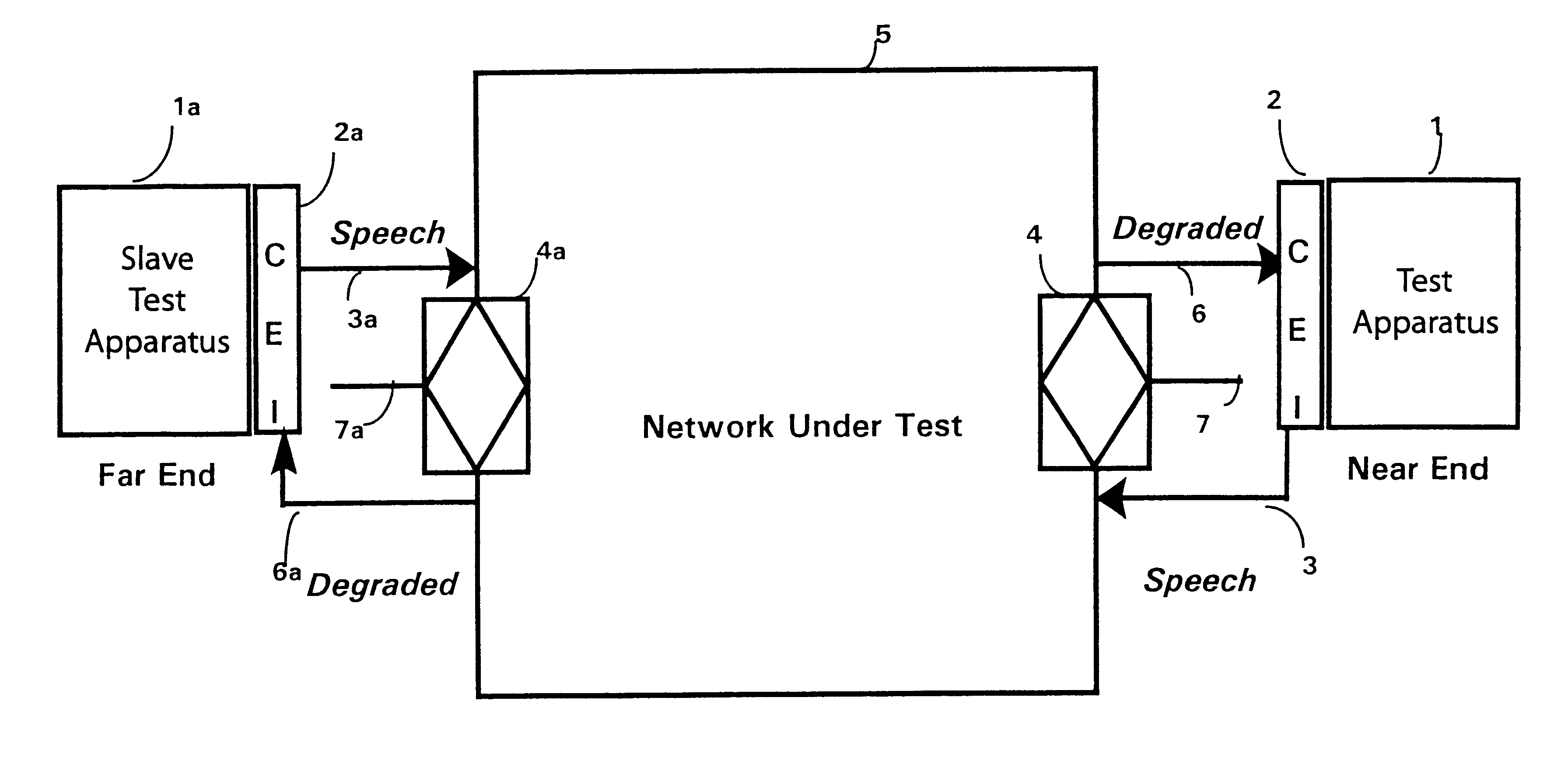
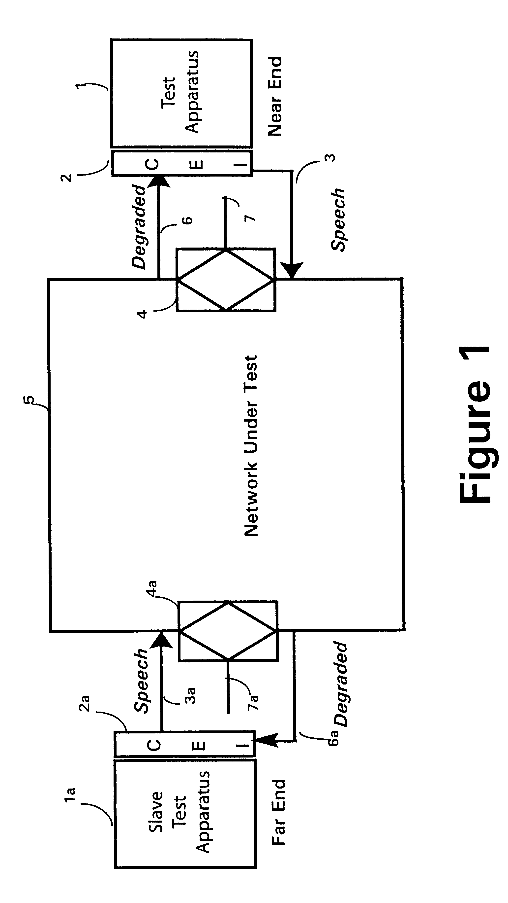
FIG. 1 schematically shows a test set-up according to the invention. A test apparatus 1, to be described in more detail later, is connected through a customer equipment interface 2 and a two-way connection 3, 6 to a junction point 4, and thereby to a network under test 5. At a remote junction point 4a in the network 5 a further two-way connection 3a, 6a, connects to a further customer equipment interface 2a and thus to a slave test apparatus 1a. The respective test apparatuses 1; 1a, the customer equipment interfaces 2, 2a; and the links 3, 6; 3a, 6a to the network 5 under test are substantially identical at each end.

As shown, each test apparatus 1, 1a is connected to the four-wire side of a two-wire / four-wire junction point 4, 4a in the network, and the two-wire connections 7,7a; junction points 4, 4a; and customer equipment are all simulated by the customer equipment interfaces 2, 2a. However, in alternative arrangements one or both customer equipment interfaces 2,2a may be connec...


PUM


Abstract

A test stimulus includes two signals RR, S. Signal S is transmitted to a customer equipment interface and over a system under test to a complementary remote apparatus. The test apparatus has two inputs processed by a number of functional elements. The first input is the reference signal RR. The other input is a corresponding test signal R' generated at remote test apparatus as a test signal R, identical with reference signal RR, and transmitted over the system under test via the customer interface. These two versions of the same test signal are compared. Firstly, the signals RR, R' are processed by a psycho-acoustic model, the output of which is transmitted to a perceptual layer, and then to a conversion unit which also receives a further input from a non-optimum loudness rating unit. The output from the conversion unit is transmitted to a signal quality determination unit, which also receives an input from the customer equipment interface. The non-optimum loudness rating unit processes inputs from the customer equipment interface and signal generator. During an iterative process, the signal generator receives feedback control from the signal quality determination unit. The remote test apparatus similarly receives a modified version of signal S (viz S') from the network and compares it with a locally-generated reference version SR. In an alternative arrangement the same test apparatus is connected to both test points of the network and processes both signals S and R, either serially or in parallel.

Description

1. Field of the InventionThis invention relates to a method and apparatus for testing telecommunications equipment, and in particular telecommunications equipment over which two-way speech traffic is to be conveyed. The telecommunications equipment in question may be an existing telecommunications network, or part thereof, or individual items of telecommunications equipment not currently in service, for example prototypes of new designs of equipment.2. Related ArtA number of methods for testing telecommunications equipment have been developed which monitor how the human auditory system responds to a test signal received over the equipment under test, in particular the extent to which distortions introduced by the network are perceptually significant to a listener. In particular the reader is referred to the present applicant's earlier international patent applications, numbers W094100922, W095101011 and W095 / 15035. In these systems a test signal representative of human speech is tra...

Claims


Application Information

Patent Timeline
Patent Type & Authority Patents(United States)
IPC IPC(8): H04M3/22H04M3/28H04M3/32
CPCH04M3/2236H04M2201/40H04M3/323
Inventor HOLLIER, MICHAEL PSHEPPARD, PHILIP JREYNOLDS, RICHARD JRIX, ANTONY W
Owner PSYTECHNICS
Learn More