Passive doppler fuze

a doppler fuze and passive technology, applied in the field of electronic circuits and systems, can solve the problems of no known rf fuze would suffice, and difficult destruction

Inactive Publication Date: 2002-05-21
RAYTHEON CO
View PDF10 Cites 20 Cited by
  • Summary
  • Abstract
  • Description
  • Claims
  • Application Information

AI Technical Summary

Problems solved by technology

The jamming transmitters would be small and elevated making destruction problematic.
This would add considerably to the cost of the munition in that a radar transmitter, receiver, and signal processor would typically be required.
With respect to the passive fuze approach, no known RF fuze would suffice and an active fuze would be expensive in the requirement of a radar transmitter system or other active detection methodology.
Unfortunately, the interfering jammers are anticipated to be low cost jammers deployed in large numbers.
Accordingly, the high costs associated with the above-described active fuze and precision guidance system approaches for the anti-jammer munition render these approaches impractical.
In addition, the guidance system and the active fuze approaches would also adversely impact the form factor of the solution.

Method used


Image

  • Passive doppler fuze
  • Passive doppler fuze
  • Passive doppler fuze

Examples


Embodiment Construction

Illustrative embodiments and exemplary applications will now be described with reference to the accompanying drawings to disclose the advantageous teachings of the present invention.

While the present invention is described herein with reference to illustrative embodiments for particular applications, it should be understood that the invention is not limited thereto. Those having ordinary skill in the art and access to the teachings provided herein will recognize additional modifications, applications, and embodiments within the scope thereof and additional fields in which the present invention would be of significant utility.

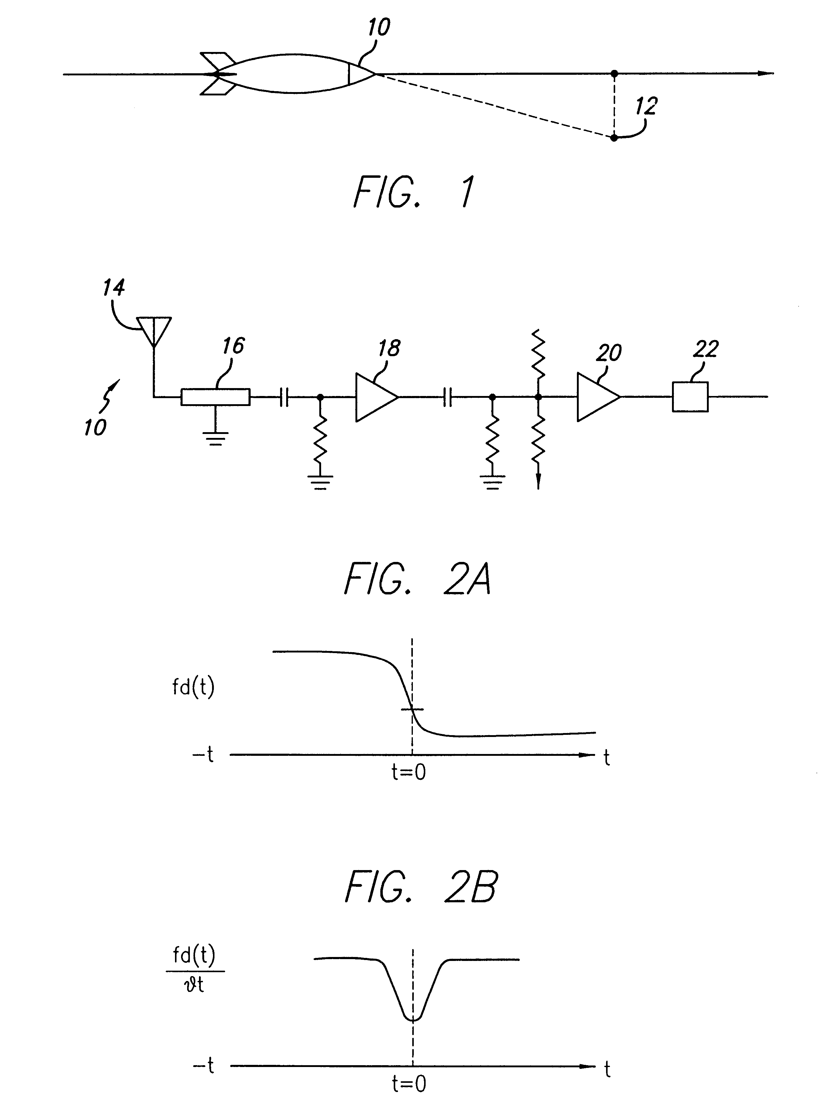
FIG. 1 is a diagram which depicts an operational environment of the proximity fuze of the present invention. The inventive fuze 10 is adapted to be used on a munition 11 for destruction of a jamming transmitter 12.

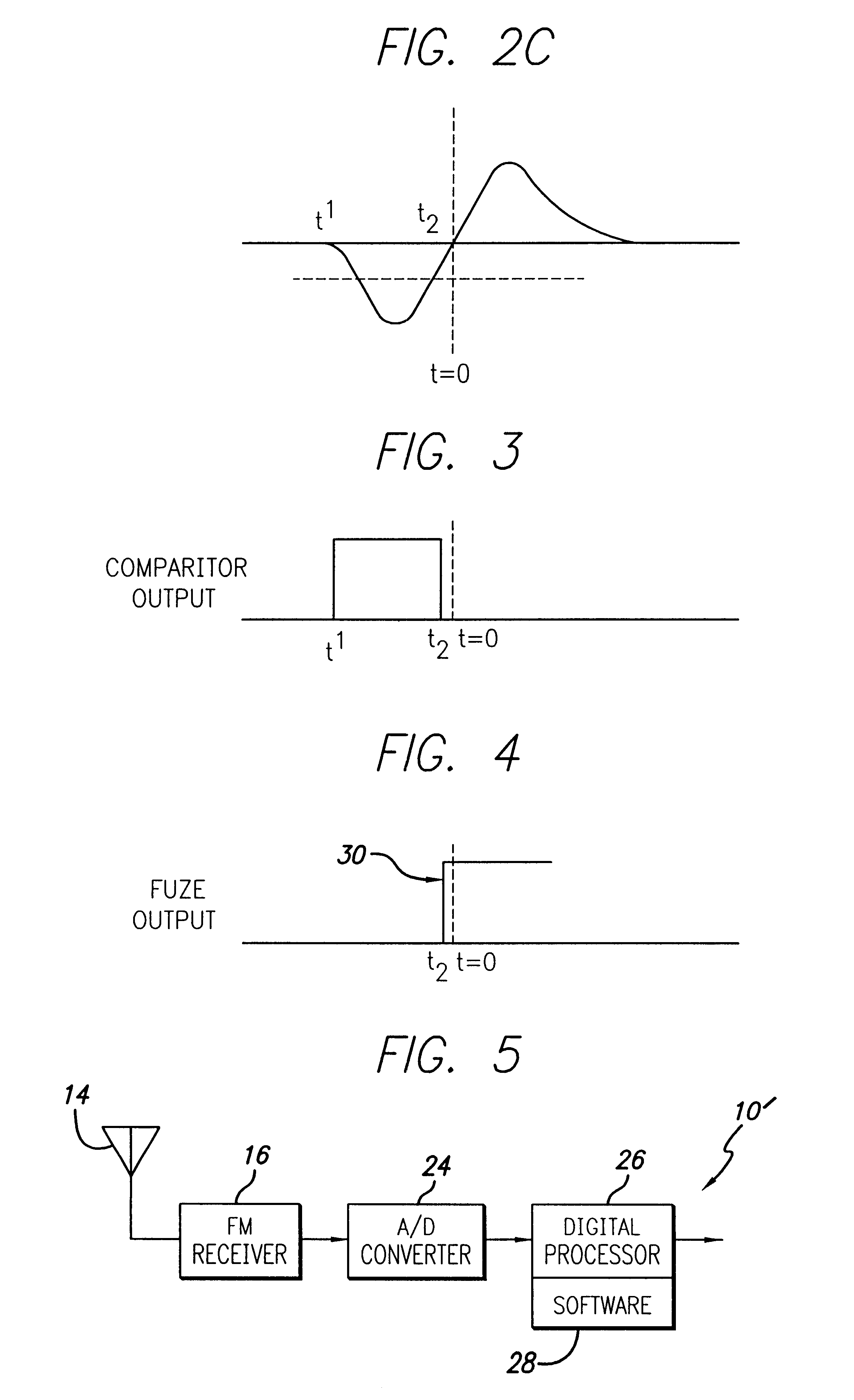
FIG. 2 is a schematic diagram of an illustrative analog implementation of the fuze of the present invention. The fuze 10 includes an antenna 14 that r...


PUM


Abstract

A passive proximity fuze. The inventive fuze (10) is adapted to be mounted on a munition (11) and includes a receiver (16) adapted to lock on to a signal transmitted by a target transmitter (12). The receiver (16) detects a Doppler shift in the signal as the munition approaches the target. When a closest point of approach is reached the Doppler shift changes from increasing to decreasing. The inventive fuze (10) includes a mechanism for detecting this change in the Doppler shift and provides a detonation signal in response thereto. In the illustrative embodiment, the receiver (16) is an FM receiver. The mechanism for detecting a change in the Doppler shift may be implemented with discrete analog circuitry or digital circuitry. In an illustrative analog implementation, first and second resistive/capacitive networks (R1C1 and R2C2) are employed to compute a second derivative of the Doppler shift signal output by the receiver (16). This signal is then amplified and thresholded to provide the output detonation signal. In an illustrative digital implementation, the output of the receiver (16) is converted to digital and processed by a digital signal processor (26). The DSP 26 computes the second derivative of the Doppler shift signal output by the receiver (16) in response to a stored program for computing same. The output of the DSP is the detonation signal. Hence, detonation is achieved at the closest point of approach of the munition (11) to the target (12) with an inexpensive passive solution (10).

Description

1. Field of the InventionThe present invention relates to electronic circuits and systems. More specifically, the present invention relates to electronic fuzes used in weapon systems.2. Description of the Related ArtFor many applications, there is a need to provide a fuze for a munition. For certain applications, a low-cost, passive proximity fuze is needed. For example, the Global Positioning System (GPS) is currently being used to provide accurate munitions guidance to target via a constellation of satellites. It is anticipated that the use of a plurality of low cost GPS transmitters may be deployed as a countermeasure to thwart the GPS guidance system of a missile or other munition in flight.Hence, there is a need for a munition capable of homing in on and destroying a GPS jammer. The jamming transmitters would be small and elevated making destruction problematic. Low cost missiles are therefore currently being considered for this application. The missiles would be traveling at h...

Claims


Application Information

Patent Timeline
Patent Type & Authority Patents(United States)
IPC IPC(8): F42C13/04F42C13/00G01S11/00G01S11/10
CPCG01S11/10F42C13/04
Inventor FOSTER, CARL G.
Owner RAYTHEON CO
Why Eureka
Try Eureka