High-pressure compressor stator

a compressor and stator technology, applied in the direction of machines/engines, liquid fuel engines, lighting and heating apparatus, etc., can solve the problems of rotor blades rubbing, increased air leakage and efficiency loss, and extremely difficult to solv

Inactive Publication Date: 2002-05-21
SN DETUDE & DE CONSTR DE MOTEURS DAVIATION S N E C M A
View PDF13 Cites 32 Cited by
  • Summary
  • Abstract
  • Description
  • Claims
  • Application Information

AI Technical Summary

Problems solved by technology

The usual problem of obtaining a correct setting of the diameters of the stator and rotor in order to avoid an excessive increase in play at the end of the blades, which would increase the air leaks and loss of efficiency or, on the contrary, would eliminate the play and cause the rotor blades to rub against the stator, then becomes extremely difficult to solve due to the uneven conditions of ventilation.
Another problem arises out of the fact that the various sections of the machine, including those that are located close to the compressor, are heated to different temperatures depending on whether they are near the ventilation air or the hotter air of the flow jet.
This results in unequal expansions, distortions and stresses within the stator.
Variations in temperature occur more quickly in certain zones such that the above problems can become more or less serious locally during phases of speed change.
No known stator structure is completely satisfactory under these conditions.

Method used


Image

  • High-pressure compressor stator
  • High-pressure compressor stator
  • High-pressure compressor stator

Examples


Embodiment Construction

, its characteristics, aims and advantages will be given referring to the figures of which:

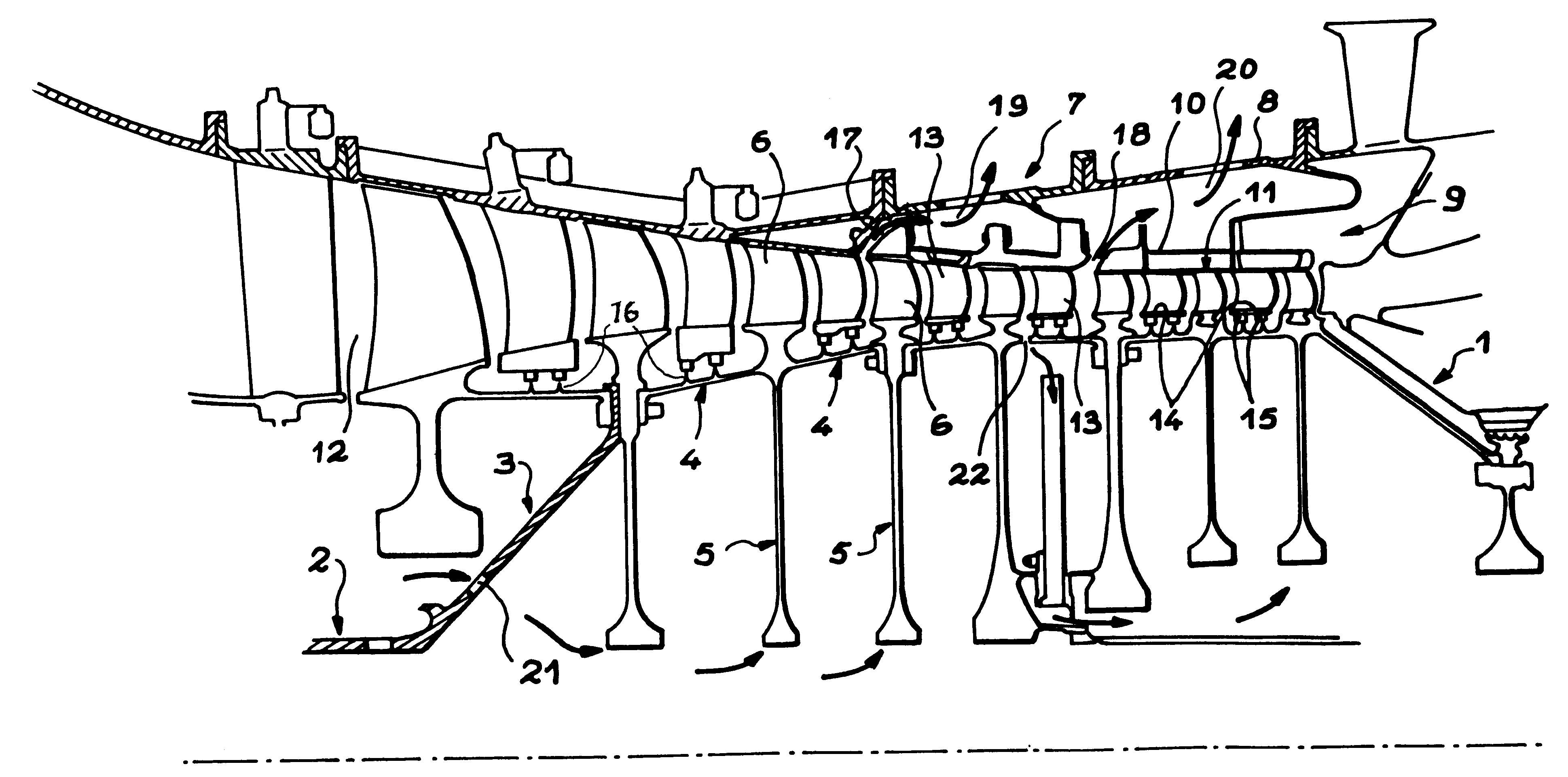
FIG. 1 is a view of a high-pressure compressor of a gas turbine engine;

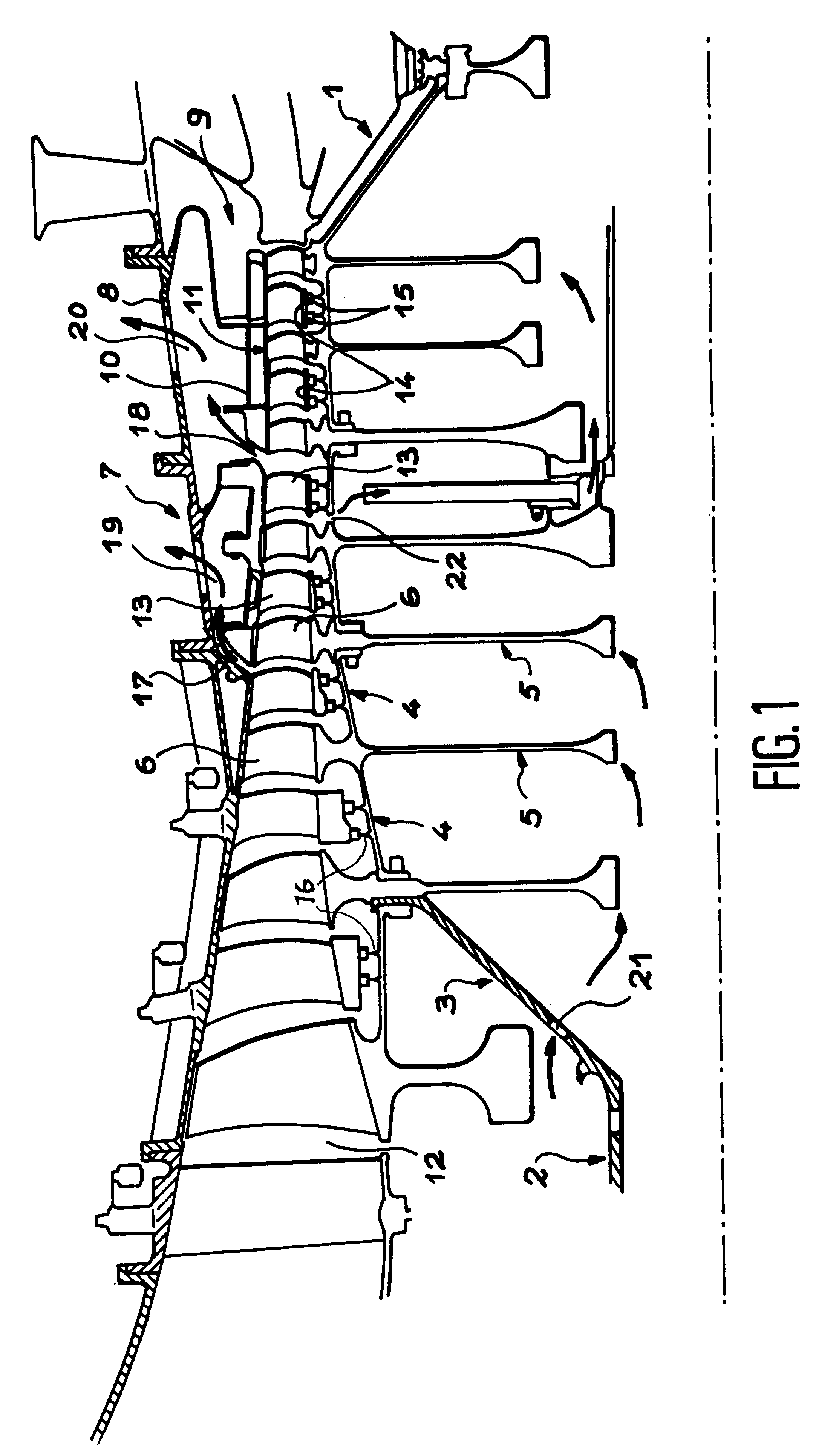
FIG. 2 is an enlarged view of the downstream section of the stator in the compressor;

FIG. 2A is a similar view of another possible embodiment of the invention;

FIGS. 3 and 4 are cross-sections of the upstream and downstream sections, respectively, of the compressor; and

FIG. 5 is an enlarged view of the upstream section of the invention.

A high-pressure compressor, such as that shown in FIG. 1, comprises a central rotor 1 driven by a line of shafts 2 and is composed of a streamlined envelope 3 consisting of rings 4 that are juxtaposed and separated by discs 5 at right angles to stages of mobile blades 6. A stator 7 surrounds rotor 1 and comprises, in the inner lining of a body 8, a section 9 to which the invention relates and that is constituted by a support casing 10 and a shroud 11 that is supported by casing 10 and turned t...


PUM


Abstract

A stator suitable for high-pressure compressors in gas turbine engines includes two points of ventilation at different temperatures. It is recommended that the upstream section of the stator be constructed with a casing and a shroud, both of which are unbroken around a circumference and made of a material with a low degree of thermal expansion. Downstream the shroud is, however, constructed using angular sectors in a material with a higher degree of thermal expansion.

Description

The present invention relates to a stator with a uniform structure capable of being applied to high-pressure compressors in gas turbine engines.DISCUSSION OF THE BACKGROUNDThe structure of the rotor and stator in gas turbine engines is often cooled or ventilated by air drawn from the flow that runs through the machine. Double ventilation may even be used in conjunction with two sources of drawn-off air or a downstream section of the stator and rotor can be ventilated after the stator and rotor have been initially ventilated further upstream. The air that is drawn off for the downstream ventilation comes from a section of the machine where it has already been compressed, thereby heating it to a higher temperature than the upstream ventilation air. The usual problem of obtaining a correct setting of the diameters of the stator and rotor in order to avoid an excessive increase in play at the end of the blades, which would increase the air leaks and loss of efficiency or, on the contrar...

Claims


Application Information

Patent Timeline
Patent Type & Authority Patents(United States)
IPC IPC(8): F01D11/08F01D11/18F04D29/02F04D29/54
CPCF01D11/18F04D29/545
Inventor GERVAIS, PASCAL GERARDLEJEUNE, PASCAL MICHEL DANIELMIRAUCOURT, CARMENNAUDET, JACKY SERGESUET, PATRICETHORE, MONIQUE ANDREE
Owner SN DETUDE & DE CONSTR DE MOTEURS DAVIATION S N E C M A
Why Eureka
Try Eureka