Tiltable arc furnace

Inactive Publication Date: 2002-05-21
ARCMET TECH GMBH
View PDF13 Cites 21 Cited by
  • Summary
  • Abstract
  • Description
  • Claims
  • Application Information

AI Technical Summary

Benefits of technology

The structure according to the invention can be implemented in existing furnaces if for example the portal has to be renewed. The stoppage times can then be substantially reduced. It is also possible without any problem firstly to convert the platform with

Problems solved by technology

That results in a statistically indefinite application of load.
Special machines are required to machine the bearing seat for the portal for that machining operation can only be effected after the welding procedure, because of the possibility of distortion.
During operation of the furnace distortion can occur because of the different effects of heat acting on the a

Method used


Image

  • Tiltable arc furnace
  • Tiltable arc furnace
  • Tiltable arc furnace

Examples


Embodiment Construction

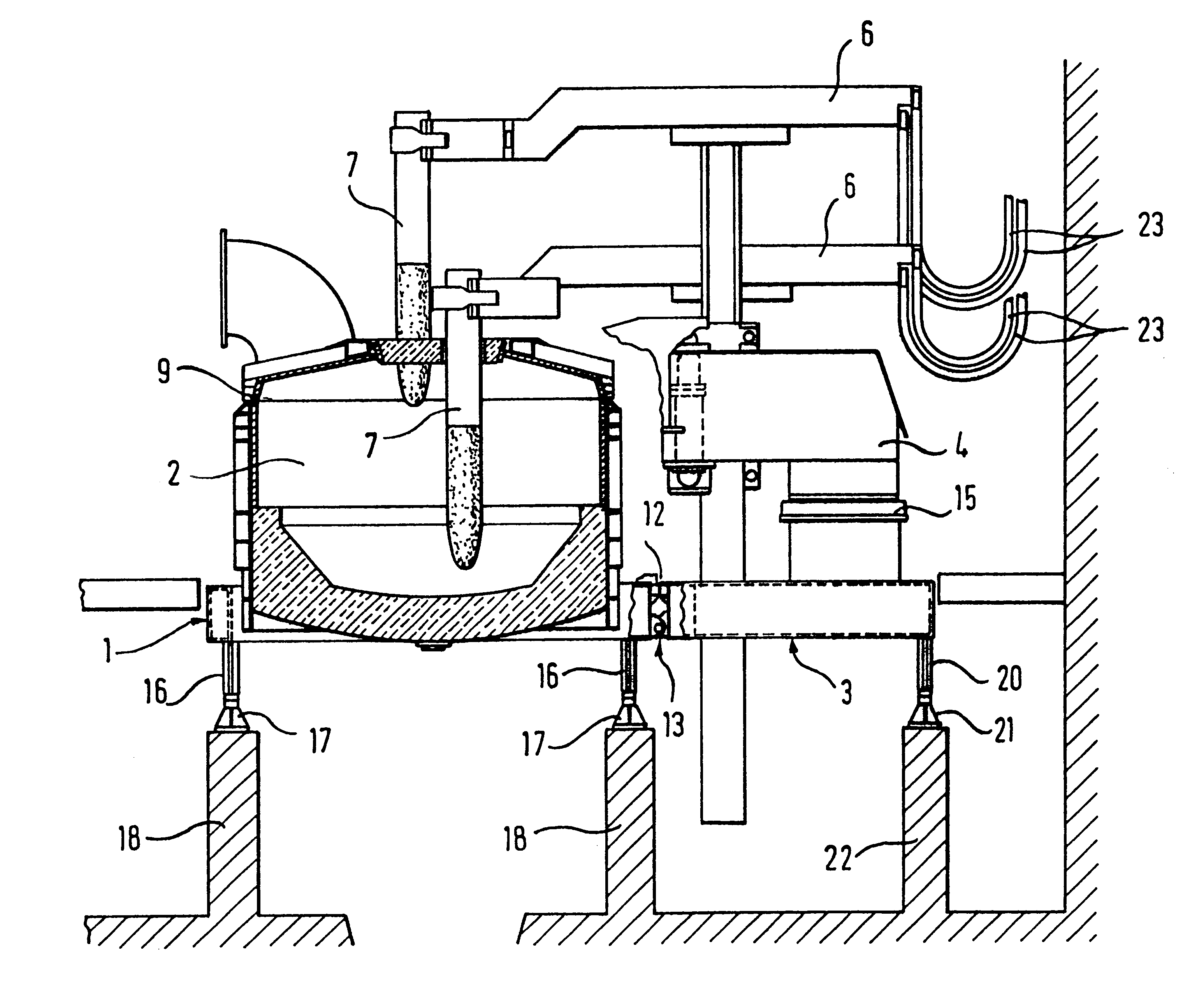
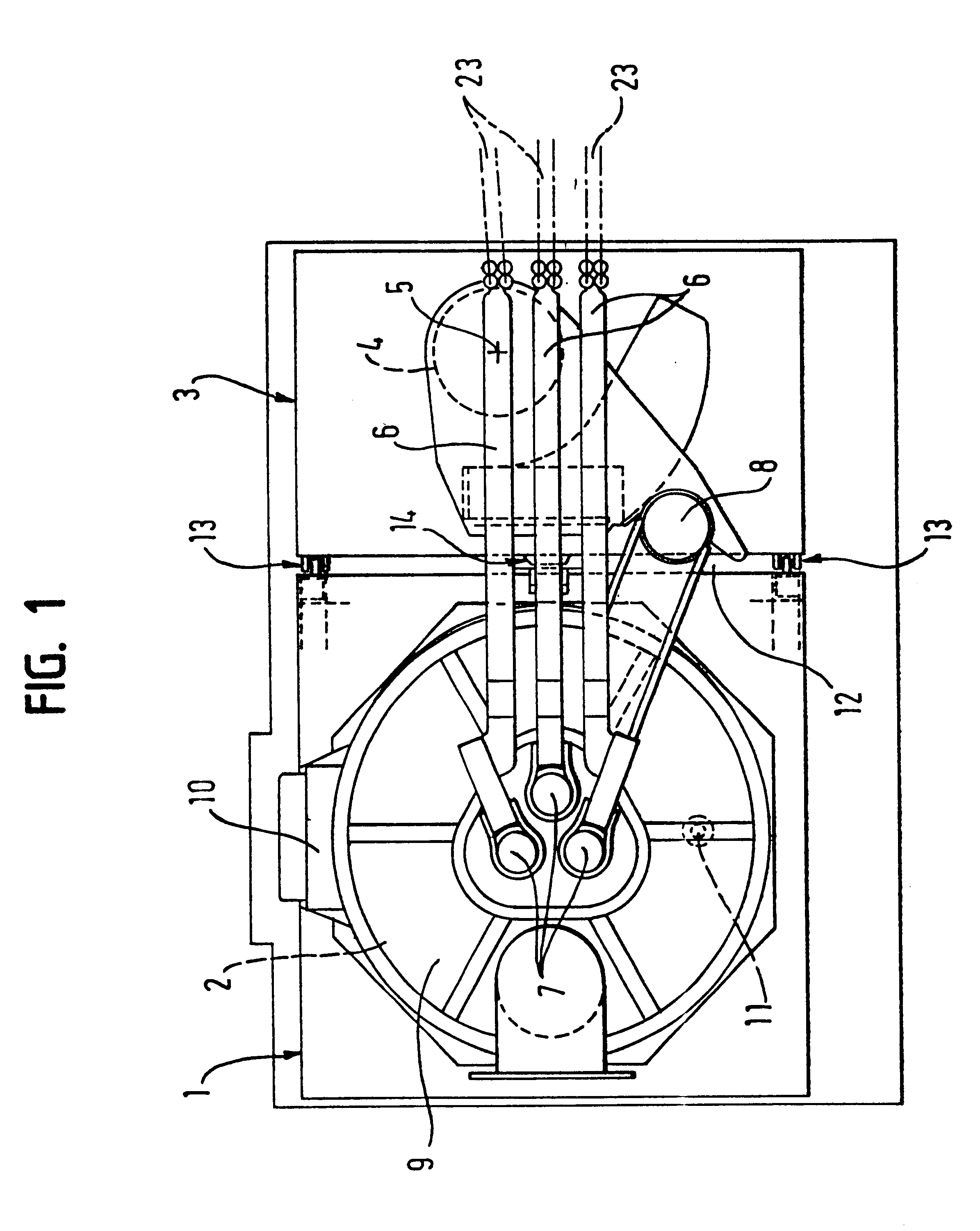
In the Figures reference numeral 1 denotes the vessel platform portion on which the furnace vessel 2 is arranged, and reference numeral 3 denotes the portal platform portion on which the portal 4 is arranged. The axis of rotation 5 of the portal 4 is arranged in eccentric relationship with the electrode carrier arms 6 which carry the electrodes 7. Reference numeral 8 represents a separate pin for lifting and pivoting out the vessel cover 9. Reference number 10 denotes the working door and reference numeral 11 denotes an eccentric bottom tapping. The platform portions 1 and 3 are separated by a gap 12 and connected by hinge pivots 13. Reference numeral 14 denotes an abutment.

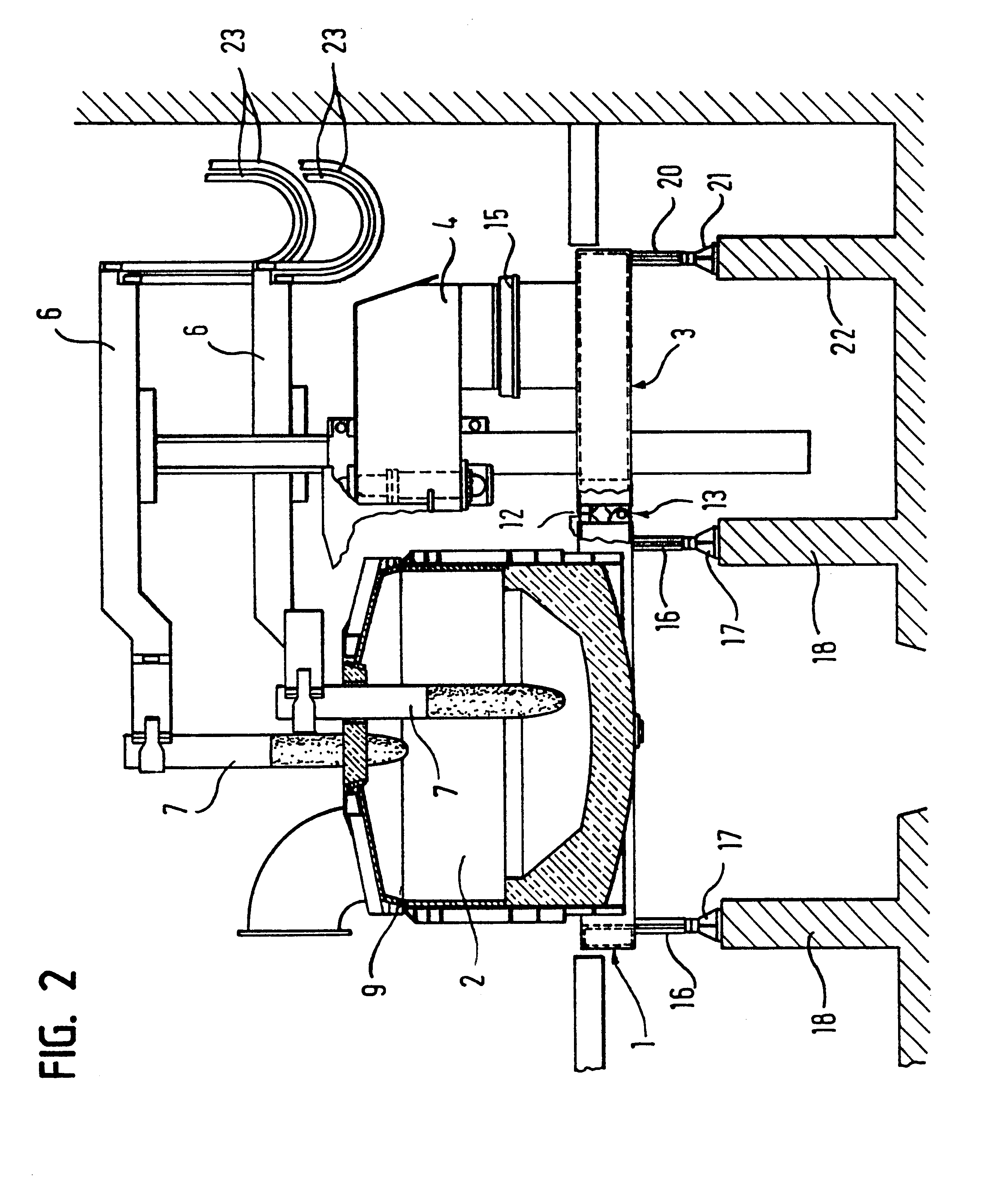
The front view shown in FIG. 2 additionally reveals the mounting 15 for the portal, as well as the two cradle runner skids 16 with the associated support paths 17 for the vessel platform portion 1 which are fixed on foundations 18. The portal platform portion 3 is supported on one of the cradle runner skids 16 an...


PUM


Abstract

In a tiltable arc furnace in which a furnace vessel (2) and a portal (4) for an electrode lifting and pivoting apparatus are arranged on a platform (1 and 3) of a furnace cradle which is tiltable by a tilting apparatus and which includes two mutually spaced cradle runner skids (16) which each run on a respective support path (17), wherein the furnace vessel (2) is arranged on a first platform region which is between the cradle runner skids (16) and the portal (4) is arranged on a second platform region which is outside the cradle runner skids (16) the two platform regions are in the form of separate platform portions (1, 3) which are connected together by a hinge pivot (13), the portal platform portion (3) carrying the portal (4) is supported by way of a further cradle runner skid (20) on a further rolling path (21) and is tiltable by the tilting apparatus synchronously with the vessel platform portion (1) carrying the furnace vessel (2).

Description

The invention concerns a tiltable arc furnace in which a furnace vessel and a portal for an electrode lifting and pivoting apparatus are arranged on a platform of a furnace cradle which is tiltable by means of a tilting apparatus and which includes three mutually spaced parallel cradle runner skids which each run on a respective support path, wherein the furnace vessel is arranged on a first platform portion (vessel platform portion) which is between two cradle runner skids and the portal is arranged on a separate second platform portion (portal platform portion) which is outside said cradle runner skids and which is tiltable by the tilting apparatus synchronously with the vessel platform portion carrying the furnace vessel.STATE OF THE ARTOf the various designs for arc furnaces, in modern furnaces the variant having a common furnace support stage or furnace platform for furnace vessel and portal has gained extensive acceptance. The furnace platform therefore also carries the portal...

Claims


Application Information

Patent Timeline
IPC IPC(8): F27B3/08F27B3/00F27D11/08F27B3/06F27B3/10C21C5/52
CPCF27B3/065F27D11/08F27B3/10F27B3/085F27B3/06
Inventor FUCHS, GERHARD
Owner ARCMET TECH GMBH
Why Eureka
Try Eureka