Auto-aspirating rotational dispersion device

Inactive Publication Date: 2002-05-28
EKATO RUHR & MISCHTECHN
View PDF16 Cites 17 Cited by
  • Summary
  • Abstract
  • Description
  • Claims
  • Application Information

AI Technical Summary

Benefits of technology

The separate guidance of the dispersed gas within the auto-aspirating dispersion device according to the invention thus assures that the device is not restricted by the predetermined gas / liquid phase ratios. The invention thereby provides an extremely capable auto-aspirating rotational dispersion device, or auto-aspirating two-phase turbine, providing a high mass transfer.
The performance of this kind of auto-aspirating dispersion device can be enhanced and its effectiveness improved by the appropriate design of its gas channels. Numerous possibilities are available here.
Furthermore, the gas channels can be designed in the form of agitator blades, to further intensify the liquid transport.
In particular, the cross-section of each gas channel opening lies on a plane running at an acute angle to the gas channel wall; the angle will ideally lie in a range from 30.degree. to 60.degree., and more specifically will amount to 50.degree.. This allows the mass transfer to be further improved due to the increased contact areas.

Problems solved by technology

At larger phase ratios the auto-aspirating two-phase turbine becomes flooded and even when the rpm is increased an increase in performance is impossible, since the aspirated quantity of gas remains at rest and an increased mass transfer is not possible.

Method used


Image

  • Auto-aspirating rotational dispersion device
  • Auto-aspirating rotational dispersion device
  • Auto-aspirating rotational dispersion device

Examples


Embodiment Construction

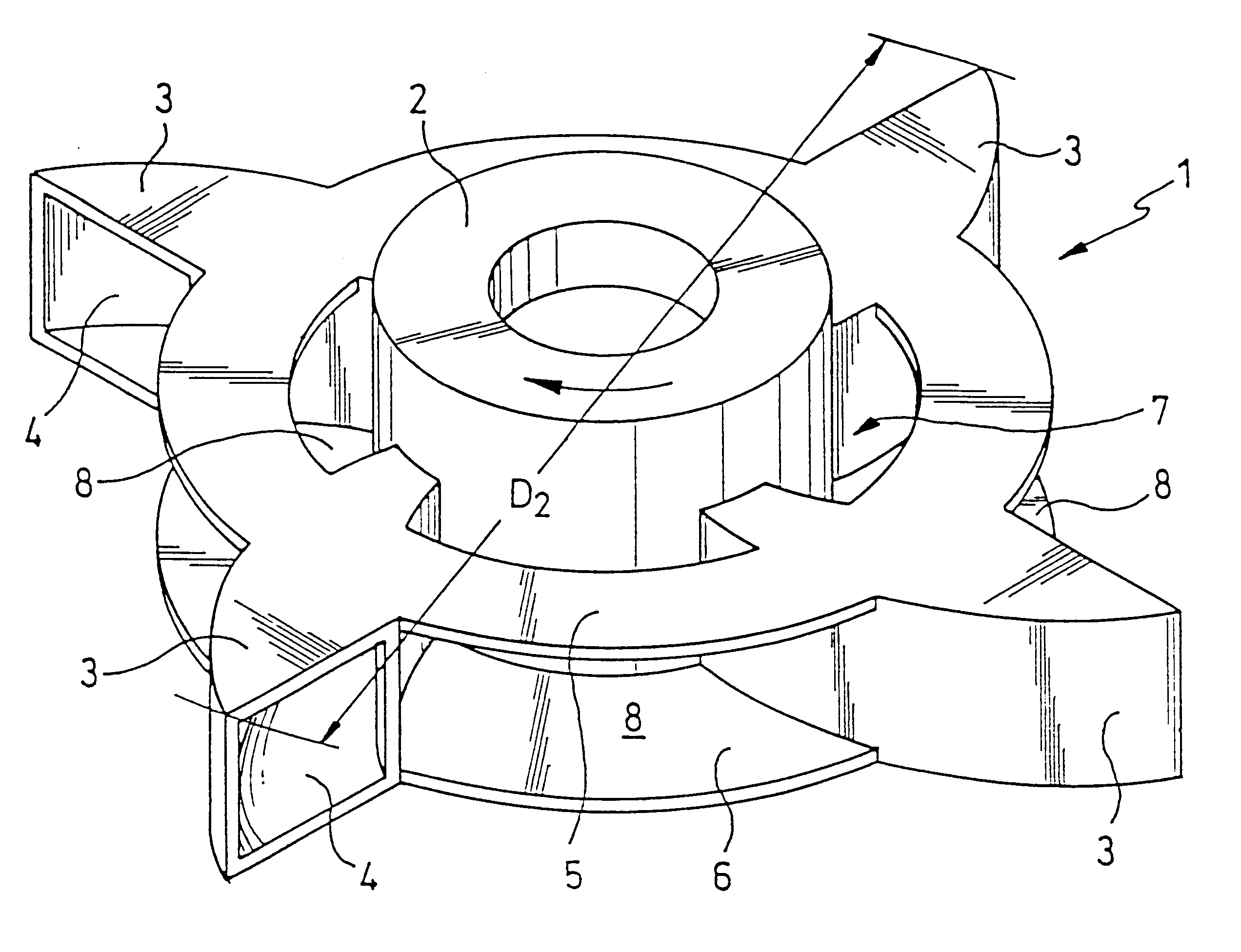
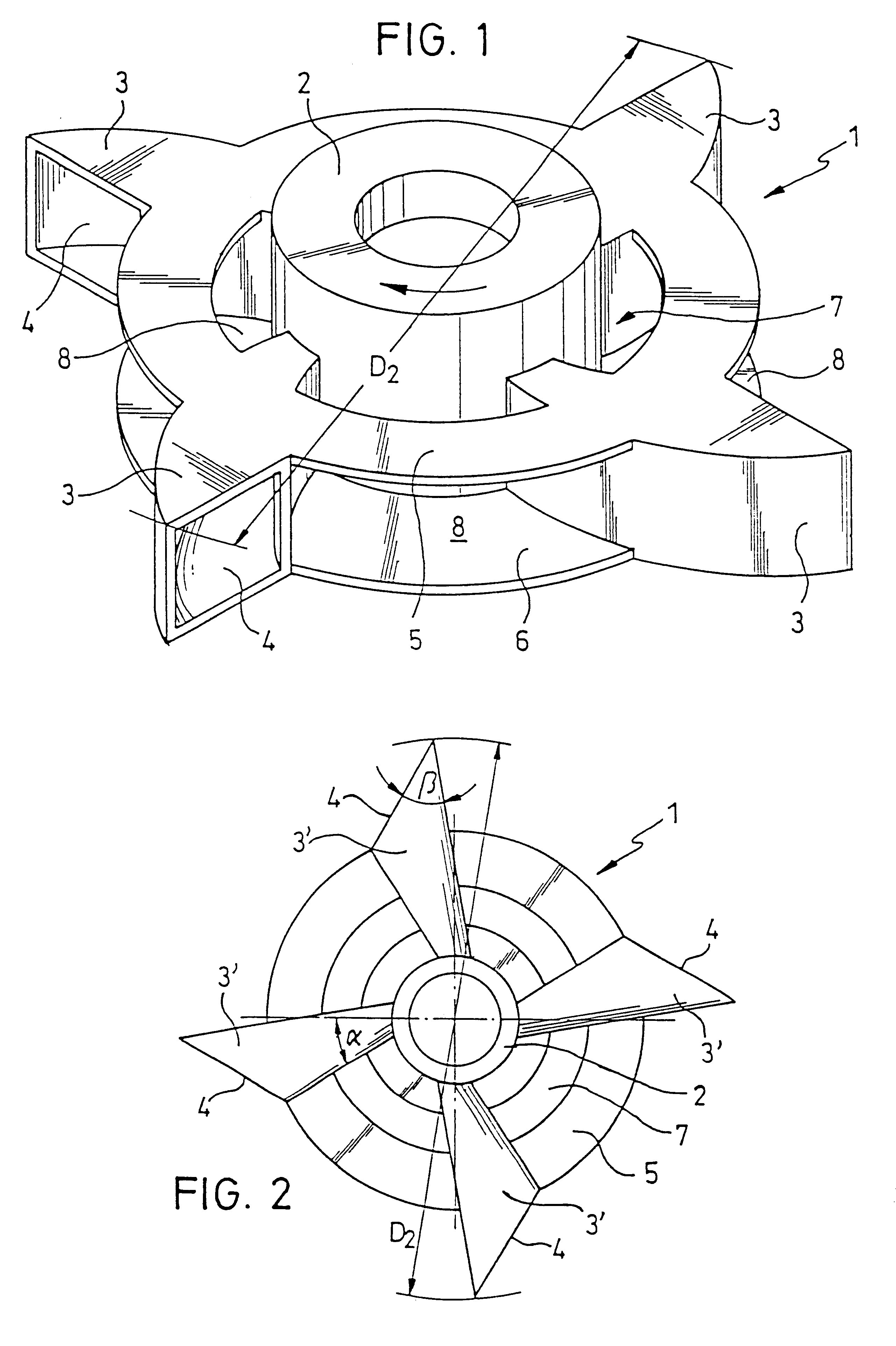
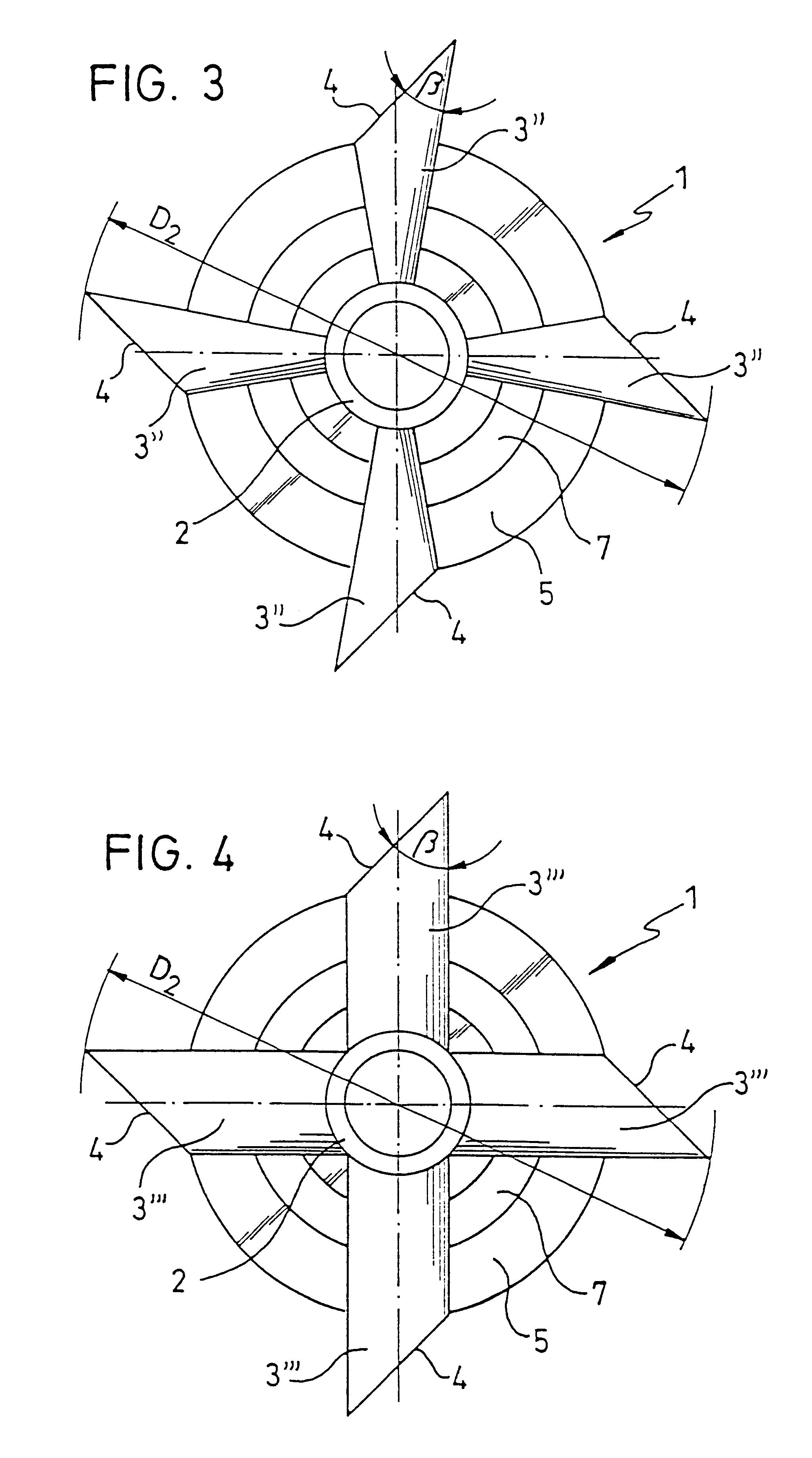
In the auto-aspirating, rotational dispersion device according to the invention, a plurality of gas channels are therefore connected to the hollow shaft; the gas being dispersed is thereby provided with an outlet through openings in the gas channels. The separation of flow creates a negative pressure at the gas channel openings which allows the gas to be aspirated from the gas chamber, against the static liquid head, through the dispersion device. The dispersion device according to the invention thereby assures continuous gas suction independent of the gas / liquid phase ratio, as based on the stall phenomenon at the gas channel opening. In the dispersion device according to the invention, moreover, the gas and liquid are mixed outside of the inner chamber of the dispersion device, specifically, in the area of the gas channel openings, since the gas channels provided by the inventive device conduct gas, but not liquid. When the dispersion device rotates, the gas channels produce inten...


PUM

PropertyMeasurementUnit
Angleaaaaaaaaaa
Angleaaaaaaaaaa
Angleaaaaaaaaaa

Abstract

An auto-aspirating, rotational dispersion device for gases and liquids with a rotating hollow shaft employed for gas suction and gas channels communicating with said hollow shaft to openings in the gas channels that are positioned at intervals over the circumference of the device, at which openings the gas and liquid are mixed. The device is distinguished by the fact that the gas being dispersed flows in a manner separate from the liquid, from the hollow shaft through the gas channels and is mixed with the liquid outside of the device.

Description

1. Field of the InventionThe invention relates to an auto-aspirating, rotational dispersion device for gases and liquids, with a rotating hollow shaft for gas suction. In particular, the invention relates to a self-priming two-phase turbine for mixing together gases and liquids.2. Description of the Prior ArtIn conventional dispersion devices or self-priming two-phase turbines of the type indicated above, gas suction occurs through the rotating hollow shaft and liquid is also introduced into the inner chamber of the turbine, with the result that the gas and liquid are mixed together inside the turbine chamber. This kind of auto-aspirating two-phase turbine works satisfactorily with a gas / liquid phase ratio of up to about 25 / 30%. At larger phase ratios the auto-aspirating two-phase turbine becomes flooded and even when the rpm is increased an increase in performance is impossible, since the aspirated quantity of gas remains at rest and an increased mass transfer is not possible. For ...

Claims


Application Information

Patent Timeline
IPC IPC(8): B01F15/00B01F3/04B01F7/00C02F3/20
CPCB01F3/04539B01F7/00241B01F7/00591B01F2003/04546B01F2003/04567B01F2003/04652B01F2003/04638B01F23/23311B01F23/23314B01F23/23352B01F23/23354B01F23/2331B01F27/111B01F27/15
Inventor FORSCHNER, PETERKREBS, RAINERWEI.BETA., HANS-JURGEN
Owner EKATO RUHR & MISCHTECHN
Why Eureka
Try Eureka