Method and apparatus for stereolithographically forming three dimensional objects with reduced distortion

a three-dimensional object and distortion-reducing technology, applied in the field of methods and apparatus for forming three-dimensional objects with reduced distortion, can solve the problems of not teaching or suggesting failing to teach a step of ensuring enough time has passed, and the technique does not teach or suggest the partial creation of laminas

Inactive Publication Date: 2002-06-04
3D SYST INC
View PDF41 Cites 84 Cited by
  • Summary
  • Abstract
  • Description
  • Claims
  • Application Information

AI Technical Summary

Problems solved by technology

This technique does not teach or suggest the partial creation of a lamina, then a delay, then the completion of the lamina.
This reference fails to teach a step of ensuring enough time has passed after exposure of a first set of vectors for the shrinkage rate to decline to an acceptable level, prior to exposure of a second set of vectors, let alone teaching the use of a device to count down a desired delay time.
In addition, this reference fails to teach a step of ensuring enough time has passed after exposure of a first set of vectors for the shrinkage rate to decline to an acceptable level, prior to exposure of a second set of vectors in a different direction than the direction of the first set of vectors, let alone teaching the use of a device to count down a desired delay time.
This reference fails to teach a step of ensuring enough time has passed after exposure of a first set of vectors for the shrinkage rate to decline to an acceptable level, prior to exposure of a second set of vectors, let alone teaching the u...

Method used


Image

  • Method and apparatus for stereolithographically forming three dimensional objects with reduced distortion
  • Method and apparatus for stereolithographically forming three dimensional objects with reduced distortion
  • Method and apparatus for stereolithographically forming three dimensional objects with reduced distortion

Examples


first embodiment

The First Embodiment

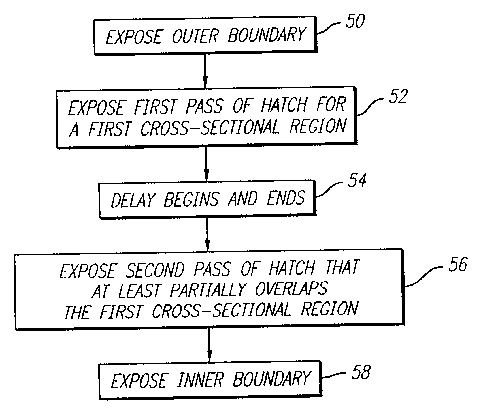
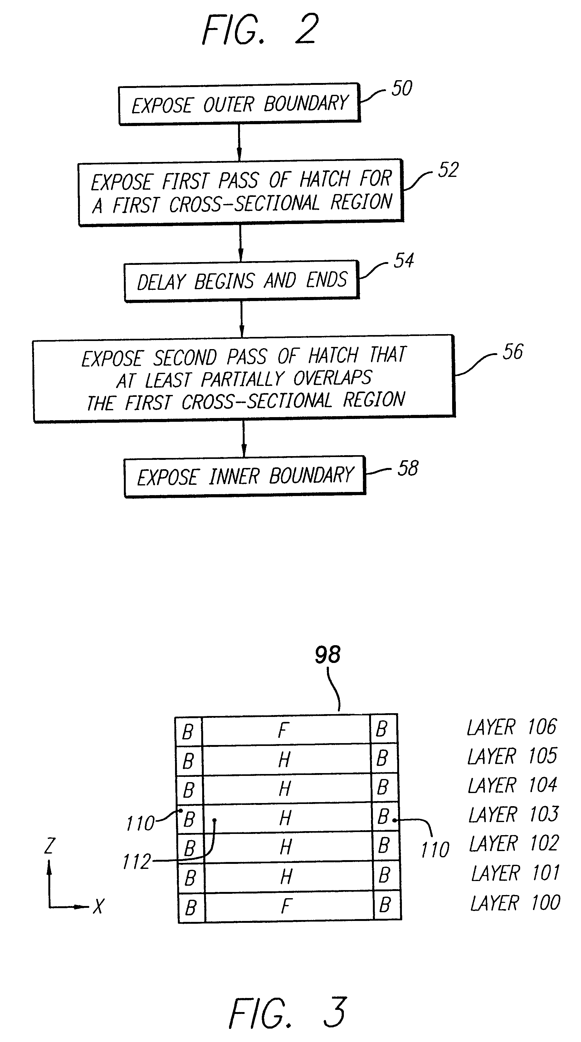
The first preferred embodiment of the instant invention involves the formation of a single object on a platform. A first hatch vector pass of the laser beam scans the object cross-section along the X-axis. Upon completion of this pass, a delay period of 15 seconds begins. When the delay period ends, layer scanning begins with hatch vectors along the Y-axis. This embodiment is depicted in the flow chart of FIG. 2.

Referring now to FIG. 3, this process is described in more detail. FIG. 3 depicts a side view of an object 98 to be produced stereolithographically. In terms of forming horizontal layers, this figure depicts the vertical axis (Z) and one of the horizontal axes (X). As illustrated, the object 98 includes seven laminae, labeled 100-106 wherein each lamina includes a boundary region labeled B and a hatch region labeled H or a fill region labeled F. Object 98 will be used throughout the description of preferred embodiments of the instant invention to illustra...

second embodiment

The Second Embodiment

The second preferred embodiment of the instant invention is a continuation of the first embodiment as applied to the formation, on one platform, of more than one object, or an object or objects with multiple cross-sectional elements. In such a situation, the techniques described above in the first embodiment are simply followed for each object and / or cross-sectional element, in turn. The cure depth values, line width compensation values, and offset values used for lamina 103 in the first embodiment apply equally to the objects and cross-sectional elements of this embodiment. For clarity, this discussion will assume that two objects and / or cross-sectional elements are being built, and that they are both at a position composed of only continuing regions. The second embodiment is depicted in the flow chart of FIG. 4.

To begin, the outer boundary is completed for the first object and / or cross-sectional element (reference element 120, FIG. 4). Then the first and secon...

third embodiment

The Third Embodiment

The third preferred embodiment of the instant invention is also a continuation of the first embodiment as applied to the formation, on one platform, of more than one object, or an object or objects with multiple cross-sectional elements. Therefore, this embodiment is, in effect, an alternative to the second embodiment. The cure depth values, line width compensation values, and offset values used for lamina 103 in the first embodiment apply equally to the objects and cross-sectional elements of this embodiment. For clarity, this discussion will assume that two objects and / or cross-sectional elements are being built, and that they are both at a position composed of only continuing regions.

A first implementation of the third embodiment is depicted in the flow chart of FIG. 5. First, the outer boundary 150 of the first object and / or cross-sectional element is drawn. Then the outer boundary 152 of the second object / element is completed. Next, the first pass of hatch v...


PUM

PropertyMeasurementUnit
Timeaaaaaaaaaa
Timeaaaaaaaaaa
Timeaaaaaaaaaa

Abstract

A rapid prototyping and manufacturing (e.g. stereolithography) method and apparatus for making three-dimensional objects on a layer-by-layer basis by selectively exposing layers of material to prescribed synergistic stimulation including forming portions of a lamina using a first exposure, allowing a time delay, and then applying a second exposure. The time delay is sufficient to allow shrinkage of the material to occur that results from the first exposure. It is preferred that the solidified portion resulting from the first exposure does not adhere to the previously formed lamina. It is also preferred that the portion solidified by this first exposure does not adhere to any boundary region that may have been exposed and adhered to the previously formed lamina. The time delay associated with a given cross-sectional region may be occupied by exposing other cross-sectional regions. The delay may occur between two exposures of overlaying hatch or fill vectors. The delay may alternatively occur between exposure of hatch vectors and boundary vectors. The time delay may be determined by a clock, or alternatively, the time delay may be considered to have lapsed upon certain physical conditions being met, such as detecting the amount of shrinkage and determining that it has progressed far enough for the second exposure to occur.

Description

This invention relates to improved formation of three-dimensional objects from a fluid-like medium on a substantially layer-by-layer basis. The invention more particularly relates to the improved formation of three-dimensional objects by stereolithography utilizing techniques to overcome difficulties in quickly forming objects with minimized distortion.1. Related ArtRapid Prototyping and Manufacturing (RP&M) is the name given to a field of technologies that can be used to form three-dimensional objects rapidly and automatically from three-dimensional computer data representing the objects. Rapid prototyping and manufacturing can be considered to include three classes of technologies: (1) stereolithography, (2) selective deposition modeling, and (3) laminated object manufacturing.The stereolithography class of technologies creates three-dimensional objects by successively forming layers of a fluid-like medium adjacent to previously formed layers of medium and selectively solidifying ...

Claims


Application Information

Patent Timeline
IPC IPC(8): B29C41/02B29C35/02B29C35/08B29C67/00G05B19/4097G05B19/4099G06F19/00G06F17/50
CPCG05B19/4099B29C67/0066B29C64/135B33Y10/00B33Y30/00
Inventor GUERTIN, MICHELLE D.HULL, CHARLES W.NGUYEN, HOP D.
Owner 3D SYST INC
Why Eureka
Try Eureka